显示标签为“Linux开发”的博文。显示所有博文

2007年5月5日星期六

Software Radio

http://volodya-project.sourceforge.net//SR/sr.php

Overview

This is a project to create a software radio device that uses USB-2.0 to deliver raw data.

Why software radio ?

Software radio has many advantages:

  • CPU can perform a Fourier transform on the captured data and display all active stations instead of having to seek from one to another.
  • It should be possible to record multiple channels simultaneously.
  • One can use it as a digital scope - an inexpensive alternative to very nice but incredibly pricy Tek scopes.

Goals

  • Make a design accessible to determined hobbyist.
  • Use only Free Software - this is actually a non-trivial constraint as most large FPGAs require a proprietary place and route tool.

Tasks

  • The first task is to verify the delivery method for the captured data. This has been completed - see report here.
  • Second task is to build a board with both USB chip and ADC controller and demonstrate analog data capture at reasonable rates. This has been completed - see below.
  • New directions ?
    • Would be nice to see a PCI Express equivalent to FX2 chip
    • There are actually DSP chips with built-in ADC, perhaps build a board with one ?

Other projects

Take a look at gnu-radio webpage for other projects. In particular there is a board designed by Matt Ettus's group that you can buy from Ettus Research LLC website.

SR-7.0

SR-7.0 is the latest variant of FX2 chip + ADC board.

Features:

  • Two-layer 3" by 3.1" board. I had two manufactured by Futurlec for $30, shipping included.
  • Cypress CY7C68013 "FX2" USB 2.0 chip. I used a 100-pin version because it has a wider spacing between pins. They are now starting to produce a newer lower-power version, I might buy these for my next design.
  • Analog Devices AD9283 ADC chip directly connected to FX2 GPIF port.
  • Ability to use three clocks for ADC ENCODE pin:
    • internal FX2 interface clock (IFCLK) (there are two choces, but 30Mhz might not be stable enough)
    • FX2 oscillator out pin (CLKOUT) - note that its frequency depends on the speed setting for 8051 microcontroller
    • external input
  • A connector exposing supply, ground and four ADC pins: IN+, IN-, REF and REFOUT. It is useful for connecting analog frontends to ADC.
  • A connector for I2C bus provided by FX2 chip
  • The board can work from either USB or external power.
  • There are connectors exposing other FX2 input-output ports.

Pictures

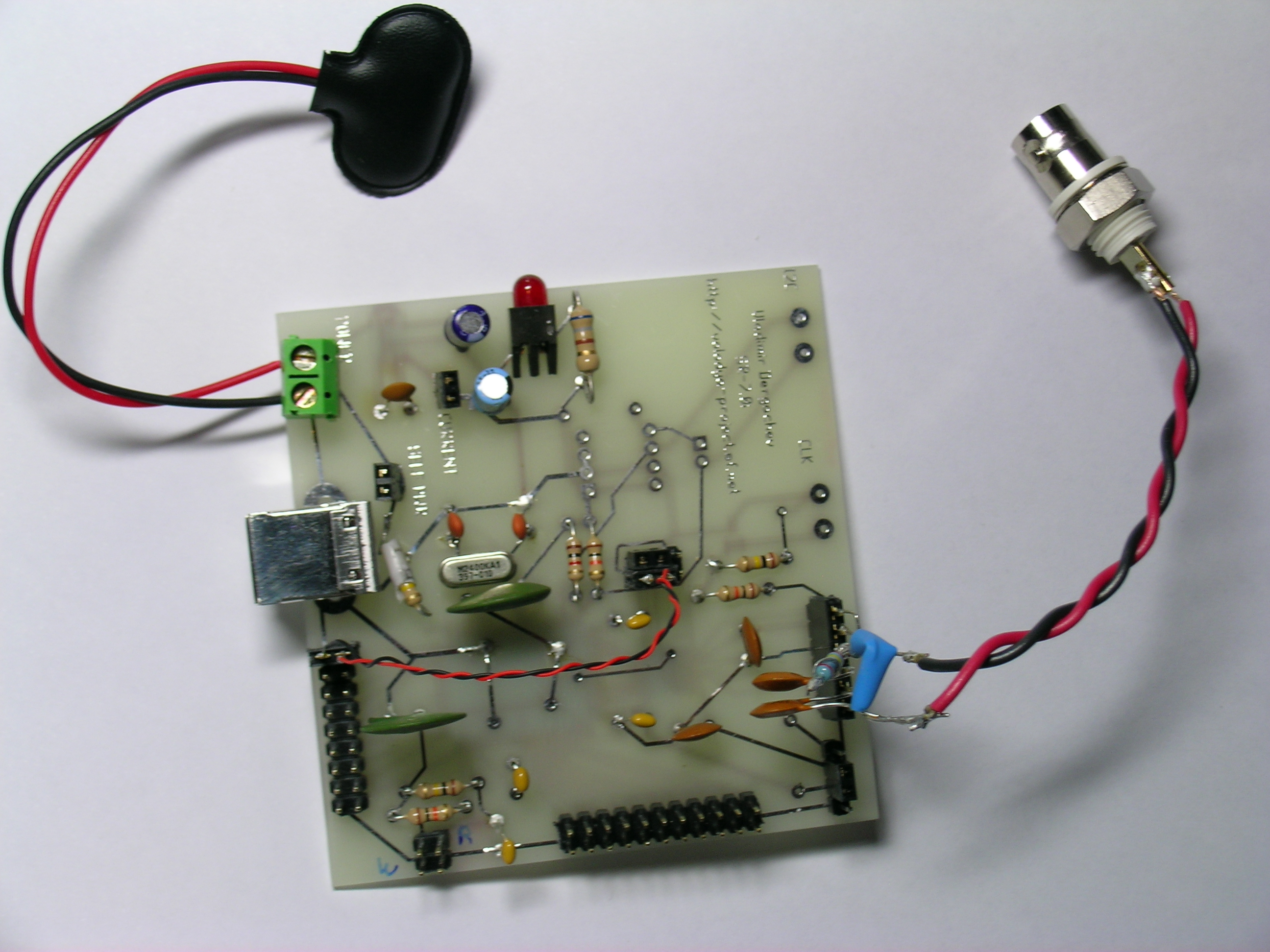
The pictures are of SR-7.0i board revision. The PCB files (below) are for later revision, with small bugs corrected (like absence of 100K resistor across USB power pins).

You can click on the images to get full-resolution pictures.

Parts side

  • The red and black braided wire connects FX2 CLKOUT pin to FX2 IFCLK and ADC ENCODE pins
  • The two jumpers in the top left corner are "SELF POWER" (to use USB power, this one is closest to the USB connector) and "CURRENT" - to make current consumption measurements
  • The absent 8-pin IC is the I2C flash chip - I just program FX2 as it comes up with default Cypress USB ids.
  • The BNC connector you see on the right is connected to simple 50-ohm "analog frontend" that configures ADC chip for single-ended operation (it is described in the ADC datasheet). This is convenient for connecting to test equipment like signal generators.
  • This layers is marked as "SOLDER SIDE" in PCB layout. This is because I was concentrated on getting connections to surface mount chips that are on the other side.

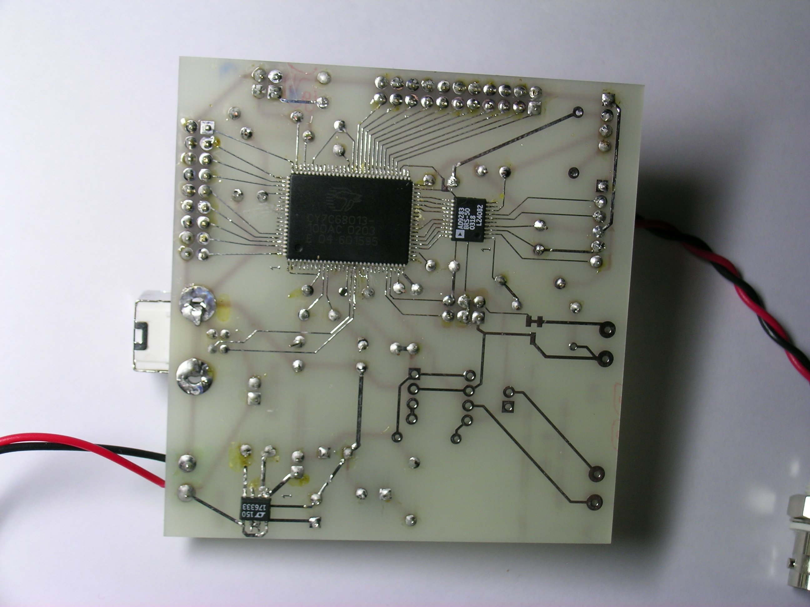
Surface mount side

  • You can clearly see CY7C68013 "FX2" chip, AD9283 ADC chip and the 3.3V voltage regulator LTC1763 made by Linear Technology
  • The toughest part of making this board was soldering the FX2 chip. I wish they came out with a package with larger pin spacing !
  • Earlier board revisions used MAXIM ADC's - these have even tighter pin spacing than FX2 and, as you can imagine, this did not work out that well.
  • When I first assembled the board it did not work - which was in stark contrast to the SR-1 project I assembled earlier. After much tinkering it turned out that if I press on FX2 chip hard enough it would show itself to USB bus. Presumably poor connections were to blame. I redesigned the board to allow for longer pads so it is easier to solder, but it is still tricky.
  • The little "1" markings show where the first pin of the IC is, so it is easier to place them correctly.
  • Note that the USB connector is on the other side.

Screenshot

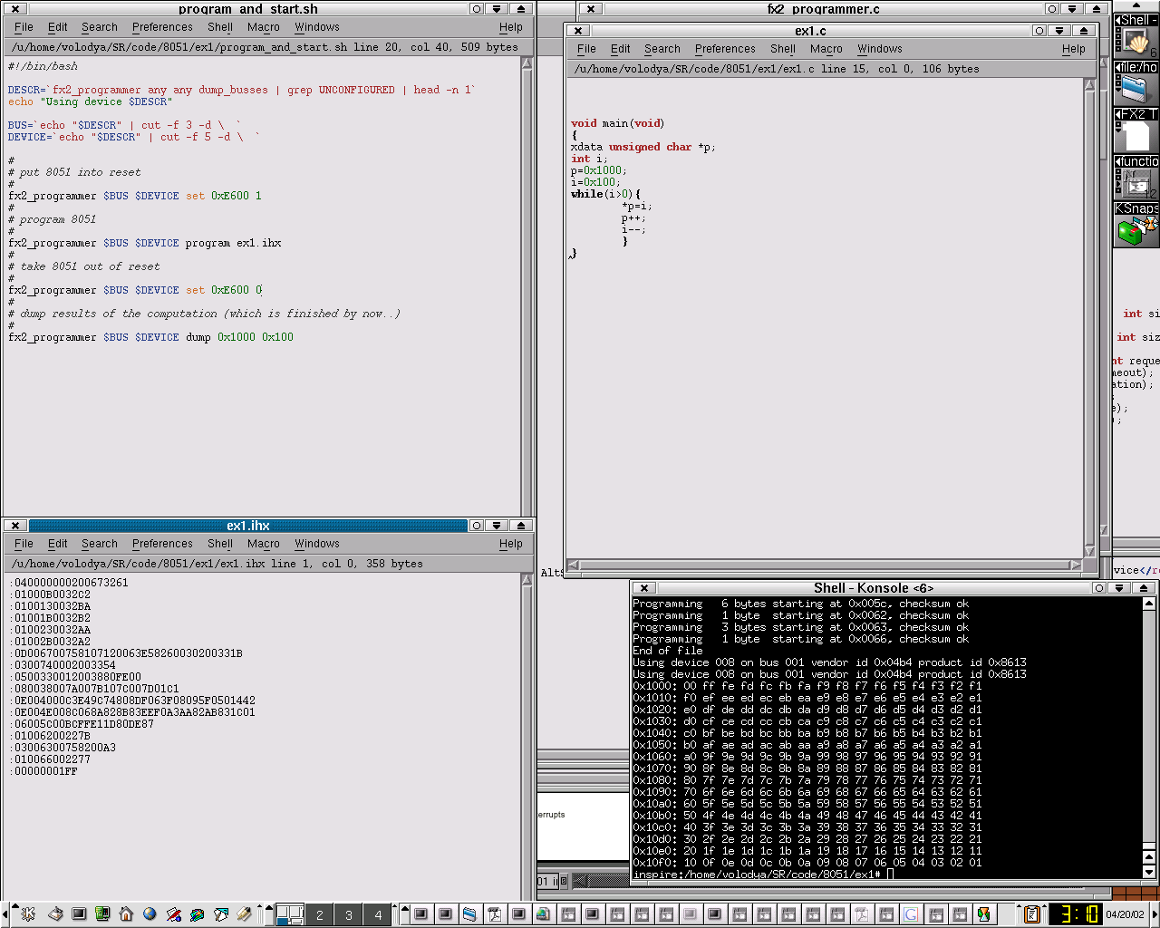
  • This screenshot shows fx2_viewer (part of fx2_programmer) displaying waveform and Fourier transform in real time.
  • Since, like fx2_programmer, fx2_viewer uses libusb for input/output I have not been able to get more than 9 MB/sec - this is less than my best number benchmarked before. Probably something inside Linux kernel or libusb has changed since.
  • The firmware running inside FX2 is available from CVS, module 8051, subdirectory SR-7.

Making your own

I have not bothered to make a schematic as the design is a straighforward combination of FX2 ATA evaluation board (chop off ATA connector) and AD9283 evaluation board (chop off all ICs except AD9283).

I did, however, write a bunch of Tcl/Tk scripts that serve a similar function (have a description of all connections) and produce a preliminary layout for PCB. You can think of them as a "TeX for boards" (note: it is *not* as easy as LaTeX so some tweaking is required to position parts and make traces).

The SR-7.0j PCB layout was created with the wonderful PCB program. Futurlec had no problem producing it from Gerber files generated by PCB. Note: I did not order silk screening, so it is somewhat screwed up on the board layout - overlaps parts, etc.

Here are some notes on board assembly in case anyone wants to tinker with their own board:
  • First, take a bare USB connector, hook it up to the cable and find the power supply pins. Your multimeter should show 5 V
  • Insert the connector into the board and check that you can see the voltage where they are supposed to be (i.e. that ground is ground). If all is ok solder the connector into place and check that it is correct and the computer does not complain about over-current conditions on USB ports (which would indicate a short).
  • Solder the parts for voltage regulator LTC1763. These are
    • REG_SWITCH jumper (short it to use USB power)
    • Voltage regulator REG (watch for pin 1)
    • Capacitors C17 (0.01 microFarad - exactly), C18 (about 4.7 microFarad), C16 (about 6.3 microFarad)
    • LED network: POWER_LED (use a small current LED) and R6 (1K) (you might want just to insert LED first to make sure the polarity is right)
    Install a jumper on SELF_PWR connector. Check that the LED lights up and you see 3.3 V - exactly !
  • Time for bravery ! We are going to solder FX2 chip parts:
    • Crystal oscillator: XTAL, capacitors C8 and C9 (22pF each)
    • I2C network resistors R10 (1K) and R12 (10K) - without these FX2 will not enumerate properly
    • Reset and wakeup networks: R2 (100K) , R5 (10K), C12 (0.1 microFarad)
    • Bypass capacitors C3, C20, C1, C19, C2 - use ceramic ones about 0.1 microFarad each. I suggest not soldering all of them at once to leave space for higher (or lower) value ones in case they are needed.
      However, solder at least C3, C20 and C19.
    • Position FX2 chip - make sure first pin is correct. Solder pins on oppossing ends and then do the rest.
    • I found convenient to use a very fine-tip soldering iron at around 275 Celcius. Just tin it and touch at the butt end of the pin until the solder melts underneath. It would help if there is a tiny bit of solder on the iron tip itself.
    • If you get solder stuck between FX2 pins just bruch with the iron tip away from the chip making sure to melt the stuck bit and clean iron tip from solder between tries.
    • When all done connect the device to USB port and check that it enumerates correctly. You can also play with FX2 chip using some of the 8051 scripts in CVS.
  • Once you know that FX2 chip is working right, solder on the rest.
    • solder the connectors for ADC, FX2 D and C ports, CLKSWITCH
    • Solder R3 (10K) and R4 (100K) resistors - they make sure ADC is powered down when the board is first plugged in
    • Solder capacitor C8 (0.1 microFarad)
    • Solder the rest of bypass capacitors - this does not hurt.
    • You can omit the drossel L1 - it is there to provide additional isolation for ADC analog supply. I found out it is not necessary.
    • Position AD9283 chip, check that pin 1 is where it is supposed to be. Solder opposing pins first. You will find this much easier than soldering FX2 chip.
    • There is a place solder EEPROM (or better yet - an IC socket for EEPROM), I did not bother with this.
    I also suggest you assemble a simple 50 Ohm frontend to connect to "ADC testpoint block". At the very least place a jumper shorting REFIN and REFOUT pins.
  • To test ADC operation you would need to program FX2 with appropriate firmware. You can find the one I used in CVS, module 8051, subdirectory SR-7. Make sure to place a jumper connecting IFCLK FX2 pin to ENCODE input of ADC. (use CLKSWITCH block). You might also want to connect CLKOUT FX2 pin to IFCLK and ENCODE (see pictures).

Parts list

  • CY7C68013 "FX2" chip - probably the most expensive part in the design. You might want to replace it with pin-compatible lower-power version (see Cypress website).
  • AD9283 ADC chip
  • LTC1763 3.3V voltage regulator
  • Connectors: USB B connector, single and double row headers. I suggest you also get some BNC socket connector (you might want to get several). Get also some RG58 BNC plugs and RG58 cable to match them. Of course, the choice of RF connector is somewhat arbitrary :)
  • 24 Mhz crystal as described in FX2 datasheet
  • Several resistors: 1K, 10K, 100K. You would want 50 ohm and 25 ohm resistors for the simple ADC frontend.
  • Several ceramic capacitors: 22pF, 0.1microFarad, 0.01 microFarad.
  • A couple of electrolytic capacitors: 4.7microFarad, 6.3microFarad. You can use tantalum if you like.
  • A small current LED - use one that lights up at 3mA.
  • A stock USB 2.0 cable (plain USB 1.1 might not work right).

Frontends

So far I only have a hastily sketched schematic of 50 ohm BNC frontend and photodiode one. Hopefully this gives some idea of how to use the board. I'll post more as they become available (perhaps learn to use gschem along the way).

Links and References

IC manufacturers

Open Source Tools

Miscellaneous

SR-1/Software Radio

http://volodya-project.sourceforge.net/SR/SR-1/sr1.php


Overview

Before implementing full blown software radio I needed to become familiar with CY7C68013 and to answer a few questions:

  • How much data can it pump thorough ?
  • How much data can linux USB driver handle without overburdening cpu too much ?

Also it would be a good idea to develop a few tools that would become useful later.

Hence, SR-1: a usb device that is just CY7C68013 without anything to pass data from.

Components

I ordered my parts from Arrow electronics website. This went ok, except that the shipping was too much. I understood why after I got three packages: a large envelope, a carton triangular box (the one to ship posters in) and a long carton box. Turns out that they shipped the parts in standard packaging, even though I ordered only few chips each. Here is a photo of the long tray CY7C68013 came in:

Image of the tray with CY7C68013 chips

Not only that, but they also shipped the parts from three different locations.

Note to self: if ordering low quantity parts from Arrow Electronics again order as few different kinds as one can and get others from someplace else that ships from a single address.

The ICs I am going to use in SR-1 are voltage regulator Linear Technology LTC1763-3.3V

Image of LTC1763 chip

and EZ-USB FX2 chip from Cypress CY7C68013

Image of CY7C68013 chip

Both are surface mount components, here is a photo of them side-by-side:

Image of all ICs used side by side

Design

Ok, this should have really preceded the component part, but I thought it would be more fun to take a look at the pictures first.

Since this would be the first time I am using these ICs and there will be plenty of corners to cut later I decided to replicate most of the Cypress ATA reference design CY4611 design, but without the EEPROM and the ATA connector.

On to soldering !

The first task was to wire up the voltage regulator LTC1763 and check that it produces the correct voltage (3.3V).

Connected voltage controller chip

one more shot of image controller

This proved easier than I thought as there was plenty of clearance between the legs of the chip. A quick test proved it functions correctly.

The hard part

Looking at the dense spacing of CY7C68013 pins prompted (yet another) trip to Radio Shack, and I purchased a "helping hands" - a kind of static holder with a magnifier glass.

Image of static holder with a magnifier lens

The grippers turned out to be really handy, but the magnifier glass needed to be too close to work to solder comfortably. It did find its use later, though.

I decided to attach wires to each pin that I am going to use first, and then attach the wires themselves to the other parts.

The first two were easy:

Image of CY7C68013 chip with two wires attached

The third was harder, and after trying to attach the fourth it came off:

Image of CY7C68013 chip with three wires attached

Time to do some thinking !

Image of me thinking

After much experimentation I decided to bend every other pin up. This increased the amount of space between pins threefold. Bending is much easier with the magnifier glass.

Image of CY7C68013 with every other pin bent up

First side had the most wires. The blue ones are for ground, red ones for power and whites ones for everything else. Since both USB and I2C are serial buses there are few white wires.

Image of CY7C68013 with one side wired up

Feeling somewhat exhausted I decided to continue with this project after a good nights sleep.

Fortunately attaching the rest of the wires did not prove more challenging

Image of CY7C68013 chip completely wired up

Assembly

Now is the time to connect everything together. This involved more soldering, during which some of the wires I so carefully attached to CY7C68013 came loose. No matter, now that I knew how to do this reattaching was trivial.

Image of SR-1 device complete

Testing

Now that SR-1 is complete it is time to plug it in.

For the first test I decided to restrict myself to USB-1.1 even though the part supports 2.0. This way I can plug it in into a USB hub which would be cheaper to replace if anything went awry. Granted, USB standard includes overcurrent and ESD protection, but some caution would not hurt. Besides, this allows me to be closer to my monitor and keyboard.

After plugging it in, Linux (2.4.16) bitterly complained about a new device that just does not want to enumerate.

After spending lots of time browsing and searching for relevant links I decided to enable debugging in USB module. Voila ! It works :))

Image of KDE USB info panel showing device connected and enumerated

Here is a shot of dmesg output:

Image of dmesg output showing the device descriptors

Apparently the debugging introduced some delays that allowed it to enumerate properly. This does not seem to be needed when connecting to USB 2.0 adaptor card so it might not be a hardware fault after all

Now that the device enumerated it was time to access its internal memory. After some quick programming I had created an fx2_programmer utility that used libusb to talk to CY7C68013.

Programming 8051

CY7C68013 contains an internal microprocessor that is opcode and register compatible with Intel 8051. Thus one can use the excellent SDCC compiler to write programs for it, instead of doing everything in machine code.

A quick update to fx2_programmer allowed me to upload Intel hex format files and test my first program that fills a predefined area with cycling integer numbers.

ex3 output screenshot

The above image is only a thumbnail, if you click on it you get the whole screenshot showing program code, compiled Intel hex format file and the dump of 8051 memory space after the program has run.

The strange xdata qualifier for the pointer p indicates that it points to the "external" memory. The reason is that 8051 is an 8 bit microprocessor and the most you can address with 8 bits is 256 bytes.. But read the manual to get the details - they are fun :)

Benchmarks

Now that everything works it is time to do some benchmarking. I connected SR-1 to ehci adaptor (no need to turn on debugging here) and wrote a small C program instructing 8051 to fire up bulk out buffers as soon as it can (ex3 in the 8051 code tarball). The best result I got was around 4 MB/sec - achieved but eliminating all 8051 code, including the NOPs recommended by the datasheet.

It turns out that changing packet size from 512 to 64 in ex3.c has little effect on the throughput. However, when I instruct fx2_programmer to read in 64 byte chunks instead of 512 the rate slows down to around 512 KB/sec.

Increasing chunk size beyound packet size yielded rediculous results - rate in excess of 50 Mb/sec for chunk size 65536.

After some digging it looks like something among usb driver and libusb screws up when user application requests to receive more than 64 byte packets, but the USB device only wants to send data in 64 byte chunks.

When I changed ex3.c to send data in 512 byte packets again things became more sensible and the rate peaked at 16 MB/sec with chunk size 2048 bytes.

The cpu utilization was quite small - less than 5%

Conclusion

The device functioned correctly. The achieved throughput rate was quite respectable and sufficient for real time data capture. The system remained almost idle during transfers.

Links and references


Linux and USB 2.0

Linux and USB 2.0

Last Update: 29 November 2004

This is a short writeup explaining what USB 2.0 changed and what's going on with it in Linux. It starts by talking about user visible changes (including usbfs information) followed by driver-visible ones. Finally it summarizes the current state of Linux USB 2.0 driver support in recent 2.4 and 2.6 kernels. If you want assistance getting this working on your hardware, try the linux-usb-users (or linux-usb-devel) mailing lists at http://www.linux-usb.org.

If you're a 2.4 user, use 2.4.22 or newer kernels. Newer kernels (including 2.6.x ones) have updates which seem to resolve the worst problems reported. The driver version string should be no older than June 2003. (VT6202 problems may still remain, especially on 2.4 kernels.)

Some older Linux distributions ship 2.4.18 kernels with EHCI code based on much older code, similar to what was in 2.5.2; the newer code supports more hardware, fixes bugs, is smaller, and has other goodness. If you're building a distribution, avoid using such old code; in particular, 2.4 versions of the EHCI driver are no longer being kept current.

You should probably know that "USB" is an abbreviation of the Universal Serial Bus, which is widely used for peripherals in modern desktop systems. (It's not "universal" in the sense that you'd want it instead of HyperTransport!) PCs typically support one or more USB controllers (one per "USB bus") each of which can support up to 127 different USB peripherals. "Legacy free" PCs omit non-USB peripheral support (like RS-232 serial lines, and PS/2 ports). Partially excepting the new USB 2.0 "OTG" support, USB is asymmetric. For example, its cabling is always asymmetric (even with OTG), so you can't hook things up incorrectly. USB supports "hotplugging" for all its peripherals, which means that you don't have to configure them by hand and that peripherals may rely on power delivered through USB. Both those features help reduce end-user setup and configuration problems, which was a major goal for USB technology.


OS-Neutral Changes in USB 2.0

Today, most USB peripherals and hosts support USB version 1.1, which supported two device speeds: low speed at 1.5 Mbit/sec, and full speed at 12 Mbit/sec. USB 2.0 is appearing in current product designs, and one of its main features is adding a new speed: high speed, at 480 Mbit/sec.

To put it another way: USB 1.1 was OK for low speed devices like mice and keyboards, and even for medium speed ones like Ethernet (10 Mbit/sec) adapters, or consumer electronics gadgets that only exchange a few megabytes of data (like many digital still cameras and MP3 players). USB 2.0 "full speed" or "low speed" is effectively just the familiar old "USB 1.1". You need USB 2.0 high speed to get reasonable speed for multiple large transfers as with some PC peripherals like disk drives (including MP3 jukeboxes :) or high resolution webcams (USB video), or get concurrent use from a bunch of 100BaseT networking adapters.

OK, it's faster! ... but what else will a Linux user notice about USB 2.0? We'll go from the outside in: starting from what you'll see with product boxes, and then working toward what you'll see with normal Linux user mode tools. (More technical details are in later sections.) One thing you won't notice is designed-in compatibility problems. Apart from some constraints on how you set up high speed devices, all your USB 1.1 hardware works just fine with USB 2.0 systems.

Updated USB Logos

One thing that you should watch for, and use to your advantage, is a new testing and branding program. Earlier USB peripherals sometimes had compatibility problems, and the tighter electrical requirements of USB 2.0 could have aggravated that issue. Instead, there are new USB 2.0 logos and a testing program that must be passed before peripherals are allowed to use them. That is, this isn't purely a marketing gimmick, there's actually some value wrapped up in this logo. Here are the new and old USB logos:

New USB 2.0 Logo
high speed labeled by the top stripe ... the two-color version highlights that in red, sometimes it's one-color.
Old USB 1.1 Logo (no compatibility testing done)

Be cautious about "high speed" peripherals that for any reason don't display that new logo. Those devices may not work very well, and it'll be your fault for encouraging vendors that sell nonconformant devices.

Hubs and Cabling

One big win for the USB 2.0 upgrade is that cables don't need to change. With the possible exception of some low quality cables that may not even handle USB 1.1 very well, you can keep using your existing USB cables. There was no need to switch to optical signal transmission, or anything similarly incompatible. There are new "Mini-B" cables, that can help eliminate the need for proprietary connectors on many small USB peripherals. (Think of a camera, cell phone, or PDA; classic B sockets take up way too much space.) However, some people report they need to avoid using long USB cables. If you're using long cables and having problems enumerating, try using shorter cables.

USB 2.0 hubs are special. Not only do they support high speed devices (older USB 1.1 hubs can't), but also because they all include "transaction translator" support that helps prevent full and low speed devices from wasting most of the USB bandwidth. See the later section on backwards compatibility for information about how this impacts end users with high speed buses whose devices may not all operate at high speed.

USB "On-The-Go" (OTG)

There is also a supplement to USB 2.0 called USB "On-The-Go" (OTG) which supports point-to-point peer style hookups for USB devices that are often used without a PC host. Few end-user OTG products exist yet; newer embedded Linux systems can be used to implement them. OTG relies heavily on those new USB "Mini" connectors, and supports low power operation (battery friendly). It also defines a modified USB 2.0 logo:

USB OTG Logo
full-speed version
(without high speed top stripe)

The key change in OTG is defining a new "Dual-Role" type of peripheral, which can become a low-power USB host when you connect it to another peripheral. Most OTG-capable peripherals will have special Mini-AB sockets (new in OTG). Because of how the USB "mini" plugs and jacks work, Mini-AB sockets accept either the Mini-B peripheral jack at one end of a USB cable or the (new in OTG) Mini-A host jack at its other end. Use the peripheral end, and they start out as a peripheral. Use the host end, and they start out like a USB host ... so that you could print directly from your camera or phone, hook a keyboard up to your PDA, or swap songs with your friend's MP3 player. If you connect two different dual-role devices, the "wrong" one may be initialized as the host. In that case, the optional OTG Host Negotiation Protocol (HNP) lets devices switch roles between "host" and "device" instead of forcing users to switch the cable around.

Host Controllers and Backwards Compatibility

You can connect USB 2.0 peripherals to USB 1.1 hosts and hubs, and they should work just fine ... but at 12 Mbit/sec, not at 480 Mbit/sec.

To get "high speed" behavior you'll need an updated host controller. It must support "USB 2.0 high speed", through the "EHCI" standard. Today you can get those as PCI cards, usually with a three or five port controller from NEC, or sometimes a four port one from Philips or VIA. More importantly, essentially all current generation PC motherboard silicon includes an EHCI controller built in. Linux users have reported success on most of these, with chips from ALI, Intel, NVidia, SiS, VIA, and others. (That's in alphabetical order; I'm not intending to slight any vendors.) See the section on Linux support (later) for more specific information.

You may also need newer hubs with USB 2.0 support. Probably the most important aspect of such hubs is how they support trees of devices that mix both high speed and full (or low) speed devices. The short version of the story is that to get high speed transfers out of a high-speed capable device, you must hook it up through an EHCI controller (that's using an EHCI driver!), and any hubs between the host and the device must only be USB 2.0 hubs.

That is, a tree of USB devices can start out with a high speed root hub, but if you plug in any USB 1.1 hubs to that tree, USB devices on branches below that hub will only operate at slower full/low (USB 1.1) speeds ... even if it's a USB 2.0 device. For now the lesson is that if you want to use a device at high speed, double check it after cabling things up. You can do this with "usbfs".


Changes Visible to Linux Users

Beyond those general issues, Linux users will notice a few changes if they poke around through what the kernel tells them about their hardware.

"usbfs" and /proc/bus/usb/devices

You may know "usbfs" through its original, and somewhat confusing name, of "usbdevfs". The name changed because it was completely unrelated to "devfs".

If you use "usbfs" (perhaps through scripts like usbtree or tools like usbview) you will notice a few minor changes. Most notably, the USB version for some devices will be "2.0", and those devices will report their speed as "480Mb/s" when they're running at high speed. (In compatibility mode, at full speed, they'll say "12Mb/s".) Here's what usbtree shows for some full speed devices hooked up to an USB 2.0 controller. Several are connected through a USB 2.0 hub, and there's a USB 1.1 hub (with no devices) hooked up to another root hub port.

/:  Bus 03.Port 1: Dev 1, Class=root_hub, Driver=ohci-hcd/2p, 12M
/: Bus 02.Port 1: Dev 1, Class=root_hub, Driver=ohci-hcd/3p, 12M
|__ Port 1: Dev 2, If 0, Class=hub, Driver=hub/4p, 12M
/: Bus 01.Port 1: Dev 1, Class=root_hub, Driver=ehci-hcd/5p, 480M
|__ Port 2: Dev 2, If 0, Class=hub, Driver=hub/4p, 480M
|__ Port 1: Dev 3, If 0, Class=>ifc, Driver=pegasus, 12M
|__ Port 4: Dev 8, If 0, Class=hub, Driver=hub/3p, 12M
|__ Port 1: Dev 9, If 0, Class=HID, Driver=hid, 12M

Some of the endpoint descriptors may change. Maximum packet sizes can be bigger, and polling intervals for periodic transfers will sometimes be measured in microseconds (like 250us), not milliseconds (like 2ms), and you may even see NAK rates for bulk endpoints. For example, this descriptor is for one USB 2.0 CD-RW when it's running at high speed:

T:  Bus=01 Lev=01 Prnt=01 Port=01 Cnt=01 Dev#=  2 Spd=480 MxCh= 0
D: Ver= 2.00 Cls=00(>ifc ) Sub=00 Prot=00 MxPS=64 #Cfgs= 1
P: Vendor=05ab ProdID=0060 Rev= 2.10
S: Manufacturer=In-System Design
S: Product=USB Storage Adapter
S: SerialNumber=2201010A0247C8AB
C:* #Ifs= 1 Cfg#= 2 Atr=c0 MxPwr= 98mA
I: If#= 0 Alt= 0 #EPs= 3 Cls=08(stor.) Sub=06 Prot=50 Driver=usb-storage
E: Ad=01(O) Atr=02(Bulk) MxPS= 512 Ivl=125us
E: Ad=82(I) Atr=02(Bulk) MxPS= 512 Ivl=0ms
E: Ad=83(I) Atr=03(Int.) MxPS= 2 Ivl=32ms

Here's the descriptor for the same CD-RW when there's no EHCI driver, so it's running at full speed (may not be a good idea to burn CDs at this speed though):

T:  Bus=02 Lev=01 Prnt=01 Port=00 Cnt=01 Dev#=  2 Spd=12  MxCh= 0
D: Ver= 2.00 Cls=00(>ifc ) Sub=00 Prot=00 MxPS=64 #Cfgs= 1
P: Vendor=05ab ProdID=0060 Rev= 2.10
S: Manufacturer=In-System Design
S: Product=USB Storage Adapter
S: SerialNumber=2201010A0247C8AB
C:* #Ifs= 1 Cfg#= 2 Atr=c0 MxPwr= 98mA
I: If#= 0 Alt= 0 #EPs= 3 Cls=08(stor.) Sub=06 Prot=50 Driver=usb-storage
E: Ad=01(O) Atr=02(Bulk) MxPS= 64 Ivl=0ms
E: Ad=82(I) Atr=02(Bulk) MxPS= 64 Ivl=0ms
E: Ad=83(I) Atr=03(Int.) MxPS= 2 Ivl=32ms

Other than that "480Mb/s" speed rating, most of that per-device usbfs information will only be interesting to folk working with device drivers. That "480Mb/s" in the descriptor for your device will be a sign that you've cabled it up correctly (so it runs at high speed). But there are also differences you may notice if you look at the root hub support for each of your systems USB busses.

USB 1.1 "Companion Controllers"

Perhaps the most curious thing is that when you plug in a full (or low) speed device to a connector on your high speed USB controller, it will be connecting to a different bus than when you plug in a high speed device to that same USB "A" socket on your PC! In the CD-RW example above, the bus number changed. Sometimes the port number will also change. (OK, so maybe you wouldn't have noticed.)

That's because of how the controllers work. Here's how /proc/bus/usb/devices looks on one system with a five port NEC EHCI based controller, and nothing hooked up to it. I added some whitespace and highlighting so you can see what's going on a bit better:

T:  Bus=03 Lev=00 Prnt=00 Port=00 Cnt=00 Dev#=  1 Spd=12  MxCh= 3
B: Alloc= 0/900 us ( 0%), #Int= 0, #Iso= 0
D: Ver= 1.10 Cls=09(hub ) Sub=00 Prot=00 MxPS= 8 #Cfgs= 1
P: Vendor=0000 ProdID=0000 Rev= 2.05
S: Manufacturer=Linux 2.5.8 ohci-hcd
S: Product=NEC Corporation USB
S: SerialNumber=00:0b.0
C:* #Ifs= 1 Cfg#= 1 Atr=40 MxPwr= 0mA
I: If#= 0 Alt= 0 #EPs= 1 Cls=09(hub ) Sub=00 Prot=00 Driver=hub
E: Ad=81(I) Atr=03(Int.) MxPS= 2 Ivl=255ms

T: Bus=02 Lev=00 Prnt=00 Port=00 Cnt=00 Dev#= 1 Spd=12 MxCh= 2
B: Alloc= 0/900 us ( 0%), #Int= 0, #Iso= 0
D: Ver= 1.10 Cls=09(hub ) Sub=00 Prot=00 MxPS= 8 #Cfgs= 1
P: Vendor=0000 ProdID=0000 Rev= 2.05
S: Manufacturer=Linux 2.5.8 ohci-hcd
S: Product=NEC Corporation USB (#2)
S: SerialNumber=00:0b.1
C:* #Ifs= 1 Cfg#= 1 Atr=40 MxPwr= 0mA
I: If#= 0 Alt= 0 #EPs= 1 Cls=09(hub ) Sub=00 Prot=00 Driver=hub
E: Ad=81(I) Atr=03(Int.) MxPS= 2 Ivl=255ms

T: Bus=01 Lev=00 Prnt=00 Port=00 Cnt=00 Dev#= 1 Spd=480 MxCh= 5
B: Alloc= 0/800 us ( 0%), #Int= 0, #Iso= 0
D: Ver= 2.00 Cls=09(hub ) Sub=00 Prot=01 MxPS= 8 #Cfgs= 1
P: Vendor=0000 ProdID=0000 Rev= 2.05
S: Manufacturer=Linux 2.5.8 ehci-hcd
S: Product=NEC Corporation USB 2.0
S: SerialNumber=00:0b.2
C:* #Ifs= 1 Cfg#= 1 Atr=40 MxPwr= 0mA
I: If#= 0 Alt= 0 #EPs= 1 Cls=09(hub ) Sub=00 Prot=00 Driver=hub
E: Ad=81(I) Atr=03(Int.) MxPS= 2 Ivl=256ms

Yes, three USB buses on one controller card! (The PCI card is 00:0b but each bus has a different PCI function number.) And it looks like there's a total of ten ports (sum the "MxCh" entries saying how many children the root hubs have), not five ... how can that be?

The answer is that the two OHCI "companion controllers" are used along with the EHCI controller, and a silicon switch connects each port to only one controller at a time. When an EHCI driver runs, all ports start out connected to EHCI. When EHCI detects a full or low speed device on a port, that port is switched over to one of the companion controllers. High speed devices it keeps for itself ... so each port seems to connect to either EHCI or its companion controller (never both!) based on whether it runs at high speed or not. If there's no EHCI driver there to handle high speed devices, then everything gets treated as full or low speed since the switch won't connect things to the EHCI controller. (Companion controllers won't necessarily be OHCI; some are UHCI.)

So to fully use a USB 2.0 host controller you must still use an OHCI or UHCI host controller driver, as you've likely been doing already. And if that's the only driver you have, you can still use hardware that includes USB 2.0 support ... it just won't be as fast until you upgrade to an OS version with USB 2.0 support. In the big picture that's a great migration story for the core USB 2.0 technology: the hardware can upgrade, and the software follows later when it's convenient for end users. (Much like most vendors' stories for migrating from one generation of CPU, or instruction set, to the next one.)

The USB Host controllers in many embedded systems would rather not spend silicon for companion controllers, so some of them avoid this by embedding a transaction translator into the controller's root hub. That's not standardized, but Linux already supports one such product (from ARC).


USB 2.0 Hubs have "Transaction Translators" (TTs)

OK, this section talks about what makes USB 2.0 tricky. And it's not all that user visible, so you can safely skip reading it if you're one of the many Linux users who just wants a top quality OS (or a Free one) and aren't very concerned about all the underlying technology. If you want to skip this, remember just this one thing: hubs with more than one TT may support more active low and full speed devices, especially more webcams or audio devices.

If you're writing a device driver, you may want to know about this, since it can affect how you write your driver. At this writing, not all transaction translator features are used by Linux. Also, since those code paths aren't used much yet, a number of shortcuts have been taken, which limit throughput. (A mostly-functional patch is available for 2.6.10, removing those shortcuts.)

Split Transactions

USB 2.0 gets some of its backward compatibility through a technique called split transactions that's used in many other buses. Many disk interface technologies, for example, support concurrent requests to different devices (like USB does), and split their requests into a "start" phase, disconnecting, and reconnecting later for a "complete" phase. That lets the bus be used for other purposes while some slow I/O completes ... like a disk drive seeking and reading several sectors, or (in the USB case) like a 1.5 MBit/sec mouse delivering its motion event.

In the case of a USB 2.0 host talking to a USB 1.1 device, it does so either through a companion controller (so it's really acting as a USB 1.1 host), or through a transaction translator in a USB 2.0 hub. The host talks to the translator at high speed, and then the translator performs the full or low speed I/O to that USB 1.1 device. It buffers data in either direction as required, and later sends the results back to the host at high speed. A hub can have just one translator, or one per port. With just one translator, a hub can only use as much bandwidth as a USB 1.1 host can. With more translators, each port can use that much bandwidth.

So for example, each of the ports on the hub might have a full speed webcam, each of which is using ten megabits per second of I/O at the same time. With less capable hubs, only one port on that hub might be able to operate at that speed at a time, supporting only the bandwidth of a USB 1.1 bus.

Using Transaction Translators

From the perspective of a Linux USB 2.0 host, there are two ways it talks to USB 1.1 devices through transaction translators. Some requests do this almost transparently, like control requests and (full speed only) bulk data transfer. In those cases, the host must tell the EHCI controller that it's talking through a transaction translator, and maybe be ready to recover from some errors, but for most purposes there's control and bulk requests are completely "hands off". That means many USB 1.1 device drivers will continue to work just fine through a USB 2.0 hub ... many network adapters, modems, digital still cameras, MP3 players, disk drives, and similar devices won't need anything more.

Then there are the requests that need a lot of hands-on attention: periodic transfers like interrupt and (full speed only) isochronous ones. Because these are all reserved-bandwidth transacton types, they can't be automated as readily as control and bulk (which can opportunistically make progress whenever periodic transfers aren't active). The result is a lot of hub-related complexity in the EHCI driver, making sure that the periodic transfers are safely scheduled and that transaction translators don't get overcommited. Periodic transfers are already the most complex type in USB (though their API got simpler in the Linux kernel 2.6 series), so to some extent it's just one more consideration when scheduling,

For example, suppost a USB 1.1 periodic transfer is to be worked on every eight frames (milliseconds). That's going to go through a specific transaction translator; the transfer needs a time when that translator isn't in use, and when there's also bus bandwidth. The EHCI driver needs to schedule a "start split" (a bit in an 's-mask') sometime in one microframe, and a "complete split" (bits in a 'c-mask') in some later microframe, and ensure that between the start and completion no other request uses that translator. Isochronous transfers can be bigger, and are managed by EHCI using a different type of data structure, but in both cases you can see that there's a fair amount of housekeeping involved in tracking what requests are active.


Driver-Visible Changes in USB 2.0

The most visible change was the addition of "high speed" devices and transfers. In a Linux USB device driver, you can tell if the device is high speed (and thus whether its transfers will be at high speed!) by testing whether dev->speed == USB_SPEED_HIGH. You've been able to do that since about the 2.4.10 kernel, but you probably didn't have high speed devices to work with then.

The rules for full and low speed transfers have not changed, but some rules changed for high speed transfers. (You may have noticed some of those changes when comparing the high speed and full speed usbfs information shown above for the CD-RW.) In a few cases drivers need to have code that knows which rules apply, but mostly the changes will be transparent to correctly written drivers. Those changes include:

  • Maximum packet sizes for control transfers are fixed at 64 bytes, and for bulk transfers they are fixed at 512 bytes. For full and low speed, those limits are smaller and can also vary between devices. Don't hard-wire maxpacket sizes in drivers that will handle high speed devices (and their full-speed modes).
  • Maximum packet sizes for interrupt transfers can now be up to 1024 bytes. (For full and low speed, those limits are much smaller.) Likewise for ISO transfers (which previously had a curious 1023 byte limit).
  • There are now eight "microframes" per frame. A useful number to keep in mind is that thirteen bulk packets of 512 bytes each can be exchanged in one microframe. (At full speed, nineteen bulk packets of 64 packets could be exchanged in one frame. High speed transfers can be more than forty times faster than full speed ones!) For devices that can operate at high speed, drivers need to queue more data, both with bigger per-urb buffers and multiple urbs, to get the most benefit from that higher speed.
  • Periodic transfers can only reserve up to eighty percent of the USB bandwidth (per microframe). In USB 1.1, up to ninety percent was available.
  • Periodic transfer periods are measured in microframes, not frames. Both ISO and interrupt transfer intervals now use a log2 encoding, where previously only ISO transfers used that encoding. (Interrupt transfers can now have larger or smaller periods.) Drivers will need to interpret endpoint->bInterval differently for high speed devices, and also set urb->interval accordingly. Use usb_fill_int_urb() correctly, so this is done for you.
  • Periodic transfers can support a "high bandwidth" mode, where up to 3 packets (3KB at most) per microframe can be transferred. This shows up in a new field in endpoint descriptors. Drivers will need to interpret usb_maxpacket() differently for high speed, since that holds the new bit field as well as the original one. (With USB 1.1 devices, periodic transfers only involve one packet each period.)
  • EHCI provides less detailed error indicators than OHCI or UHCI. This means that drivers for USB 1.1 devices should retest for good behavior while connecting through a transaction translator in a USB 2.0 hub. Try things like unplugging devices while they're actively in use. It's likely they'll see EPIPE (endpoint stall) errors in some cases where previously they saw ETIMEDOUT (ohci) or EILSEQ (uhci). Unlike true endpoint stalls, usb_clear_halt() won't be able to talk to the device. (Your driver does have code to recover correctly from halted endpoints, doesn't it? It should!)

There are also protocol changes that should be invisible to most device drivers ... except in some cases for the host or device controller drivers, or the hub driver:

  • There's a new "other speed configuration" descriptor for devices that can work at both full and high speed. When a device is working at full speed, it would usually have different descriptors for high speed operation ... see the CD-RW example above. You don't need to re-enumerate at the other speed to see those descriptors.
  • "Split transactions" use a new feature of USB 2.0 hubs, the "transaction translator, which makes more efficient use of USB bandwidth. (All transactions run at high speed. Hubs build in buffering and logic for full or low speed speed operations.)
  • NYET transactions on the wire, used to detect that split transactions are not yet complete.
  • PING transactions on the wire help flow control to high speed bulk or control endpoints.
  • DATA2 and MDATA transactions on the wire are used with isochronous transfers.
  • The hub descriptor defines a few new fields, and uses the protocol number to say whether each port has its own transaction translator.

USB "Gadget" API; and OTG

As Linux gets embedded more widely inside USB peripherals (not just USB hosts), the USB "function" or "target" drivers have been getting more attention. The original Linux-USB programming interface had only a host side model: one master talking to many targets (like a web client talking to many servers). It didn't support the drivers running inside USB devices.

A peripheral side Linux-USB gadget API is now standard with 2.4 and 2.6 kernels. That framework currently supports at least a dozen different types of USB peripheral controller hardware under Linux. While it resembles the original host-side programming interfaces (at least in terms of submitting asynchronous requests, and in terms of shared core data structures), it must treat USB busses very differently from a host side API. That's because implementing the target function only involves responding to a single USB Host (like a web server only responding to one client at a time). Also, target side drivers can never initiate control requests, they can only respond to them.

Once Linux supported both "host" and "gadget" USB APIs (at all device speeds), it clearly had almost every programming interface needed to implement OTG compliant devices. Courtesy of Texas Instruments, Linux 2.6.9 kernels include an implementtion of OTG on Linux; that first implementation supports TI's OMAP processors, used in wireless devices.


Linux Status

People have been using USB 2.0 with usb-storage devices from Linux hosts since June 2001. But it was only towards the end of that year, a short while before Linus created the 2.5 development branch, that other USB 2.0 devices (notably, hubs) began to be available. So while some changes for USB 2.0 were rolling into 2.4 kernels through the year 2001, largely done by about 2.4.10, the most tricky stuff (the ehci-hcd driver) stayed separate until the 2.5 kernel branched. All current Linux distributions include EHCI support, and the end-user bug reports have been helping to stabilize that driver.

Host Controller Driver Support

At this writing the "ehci-hcd" driver is not as well proven as the OHCI or UHCI drivers, so parts of it (especially those parts interacting with USB 2.0 hubs and transaction translators) are still experimental, but it's just fine for many purposes, including espcially providing quick access to high speed disks. (Where "quick" often means up to 30 MByte/second, with off-the-shelf hardware.)

  • The Linux 2.6 kernel has the most up-to-date USB 2.0 support, as well as quite a number of other USB updates and cleanups.
  • The 2.4.19 kernel was the first to bundle a 2.4 based version of the ehci-hcd driver, but avoid using anything older than 2.4.22. Expect any 2.4 version to be less current than the 2.5 version; it's also not being updated to match 2.6 any more.
  • Older Linux distributions include a 2.4.18 based version that's much like the original 2.5 patch, though more recent distributions (including RedHat 9) match a good 2.4.21-pre level.

In terms of functionality, the latest driver:

  • Supports all four USB transfer types at high speed: control, bulk, interrupt, and isochronous. However, scheduling for interrupt transfers currently takes shortcuts which prevent them from using much bandwidth. (Or handling certain system configurations. However, a patch for 2.6.10 is being tested which removes those shortcuts.) And nobody's really done much yet with the isochronous code, although kernel 2.6.2 (or 2.4.25) and later has a rewritten version that handles high bandwidth, and is a lot more capable.
  • Has partial support for split transactions (full and low speed transfers) through USB 2.0 hubs:
    • Control and bulk transfers work, though older versions may not recover from some errors appropriately. That means: that while you should be able to use many USB 1.1 devices like disks and still cameras through such hubs, you might also run into some failure modes that can't yet be recovered. (And some device drivers might also need updates to handle new failure modes, as noted above.)
    • Full and low speed interrupt transactions work, taking the same scheduling shortcuts as high speed interrupt transfers take. So most keyboards and mice should work on USB 2.0 hubs, if you're using one of the more recent kernels. (Some serial port and Bluetooth adapters aren't compatible with those shortcuts though.)
    • Full speed isochronous transfers work somewhat through USB 2.0 hubs, in current 2.6 kernels. But they're not robust yet; for example, USB speakers will sometimes work, but there may also be an audible buzz in addition to (or instead of!) the desired sound. Eventually of course a dozen USB 1.1 webcams will easily coexist at full data rate on a single USB 2.0 bus, using USB 2.0 hubs.
  • The current kernels support BIOS handshaking (transferring "ownership" of EHCI from BIOS/SMM to Linux, as is done for OHCI or UHCI). That depends on EHCI hardware features that took time to become generally available with BIOS implementation support. Recently some BIOS versions have appeared which don't seeem to cooperate fully with Linux (mis-implementing that handshake).
  • Works with a variety of EHCI silicon implementations. NEC led the market by over a year, but now implementations from Intel, NVidia, Philips, VIA, SiS, ALI, Genesys, and others work with Linux.
  • Should tolerate more abuse on CardBus adapters. Before the 2.5.29 kernel, you needed to manually "rmmod" ehci-hcd (and often ohci-hcd) to cope with a sequencing bug in the CardBus shutdown.

You'll find that most PCI USB 2.0 add-in cards (and CardBus/PCMCIA ones) use the NEC silicon or the VT62x2, though there are other vendors. (Including ALI.) The cards that do both USB 2.0 and FireWire have for some reason been a problem for many people, even those without built-in PCI bridges. Avoid the VT6202 cards; but VT6212 should be OK.

Some folk have problems with the CardBus versions, because Linux hasn't always managed to get the IRQs assigned correctly on their particular laptop make/model. (IRQs are a general problem, BIOS and ACPI problems abound.) Once such BIOS/PCI level problems get resolved, the ehci-hcd driver works with those CardBus configurations too. It may be very important to use an external power supply for the CardBus adapter. (It seems like CardBus can't supply all of the power needed by bus-powered USB devices, without help: half an Ampere from each port. With longer USB cables, you may also need more power to drive the signals correctly.)

If you're using a CardBus adapter with an older driver version, you may need to manually remove the driver (with rmmod) before a CardBus eject (including cardctl eject) or system shutdown; the CardBus shutdown doesn't shut down drivers when it should, so that's the only "clean shutdown" solution..

See the linux/Documentation/usb/ehci.txt file in your Linux kernel source distribution for some more information. As always with drivers still in development, if you have any problems, try the latest code (preferably in the 2.5 kernel, otherwise in the latest 2.4 code) to see if the problem has been fixed yet. And if not, report problems to the linux-usb-devel mailing list.

Device Driver Support

High speed storage devices, and to some extent hubs, seem to be the most USB 2.0 devices so far. High speed scanners and printers are available, and there are early reports of success using them.

Most full and Low speed (USB 1.1) devices will work when connected to USB 2.0 root hubs, using their current drivers, since they'll be handled by the companion controllers. Many of them should also work when connected to USB 2.0 external hubs, subject to the restrictions desribed earlier. (Which, for the latest code, amounts to no webcam or audio support yet.)

Device Driver Comments
USB 2.0 hubs hub (usbcore) USB 2.0 hubs work, but haven't been widely stressed (especially in terms of faults happening during transaction translation). The hubs with Cypress hub chips have multiple transaction translators; get that kind if you're using many full speed audio or video devices.
Disks, CD-RW, USB-FLASH, etc usb-storage Linux USB 2.0 support seems to work pretty well for the usb-storage devices that now exist, though it's slower on 2.4 since the usb-storage driver does not queue its USB requests. (Where "slower" still tops 10 MByte/sec on most hardware.) Starting with about 2.5.45, storage uses the new usb_sg_submit() call to queue all I/Os in a scatterlist at once, so nothing should be in the way of letting your hardware achieve 20+ MByte/sec (except maybe bugs that aren't yet fixed, or slow disks).
BackPack USB Drives usb-storage Micro-Solutions has provided software to set up their devices with hotplugging, so that you can easily connect theeir drives to Linux. Available in several formats, including RPM.
Archos MP3 Jukebox usb-storage Older kernels may need a tweak to usb-storage error handling, or a workaround: start the Archos and let it boot up before you load or hotplug the usb-storage module..
ASIX AX88172 (10/100 Ethernet Adapter) usbnet A variety of products, including the D-Link DUB-E100, Hawking UF200, and Netgear FA120 all use this technology. Running at high speed, all of them should give much better throughput than similar full-speed products. This driver is merged into usbnet in 2.4 and 2.6 kernels.
ALI M5632 Host-to-Host Link usbnet Adapter cables based on this chip are available from several different vendors, and can provide good throughput to another Linux system.
IOGear Host-to-Host Link usbnet (patch needed) Press Release
Orange iBOT2 WebCam ovfx2, evolved from ov511 This is the first USB 2.0 webcam announced.
Cypress EZ-USB FX2 custom ... depends on what your firmware makes it do These are 8051 microcontrollers with support for high speed transfers, designed for use inside USB devices and with custom firmware. The fxload software lets you download that firmware. For the start of one interesting Linux-based example (hosted at sf.net), see the SR-1 software radio.
NetChip 2280 custom ... depends on what your firmware makes it do These are PCI based controllers with support for high speed transfers, designed for use inside USB devices and with custom firmware. Linux-USB gadget support is available, so you can implement that firmware under Linux. One such driver implemens a network interface, and others are under development.

Regardless of what type of high speed device you use, USB hotplugging works the same as it always has on Linux.

User mode device drivers should be able to use the usbfs APIs as usual. They may be able to tell that they're talking to USB 2.0 devices by details in the device descriptors (such as 512 byte bulk packets); the Java USB APIs expose such information more directly. The libusb APIs (in C) don't yet.


References

如何利用Video4Linux获取摄像头数据

Video4Linux是Linux下用于获取视频和音频数据的API接口,在这篇文章中,着重阐述如何利用Video4Linux获取摄像头数据,以实现连续影像的播放。

1. 摄像头的安装

在Linux 下常用的摄像头驱动是spca5xx, 这是一个通用驱动,读者可以在以下网站下到这个驱动 http://mxhaard.free.fr/download.html。这个网站还给出了这款驱动支持的摄像头的种类。另外,ov511芯片直接就 支持Linux,使用者款芯片的摄像头有网眼V2000。我使用的是网眼V2000的摄像头,和Z-Star 301p+现代7131R芯片的摄像头。后一种需要spca5xx的驱动。关于spca5xx的安装方法,网上有很多介绍,这里就不说了。

2. 摄像头的调试

安装好摄像头后,为了测试摄像头能否正常工作,可以用一下软件。比较著名的是xawtv,在网上搜以下可以下载到。安装好后,打开xawtv则可以调试摄像头。

3. Video4Linux 编程获取数据

现有的video4linux有两个版本,v4l和v4l2。本文主要是关于v4l的编程。利用v4l API获取视频图像一般有以下几步:

a> 打开设备

b> 设置设备的属性,比如图像的亮度,对比度等等

c> 设定传输格式和传输方式

d> 开始传输数据,一般是一个循环,用以连续的传输数据

e> 关闭设备

下面具体介绍v4l编程的过程。首先指出,在video4linux编程时要包含头文件,其中包含了video4linux的数据结构和函数定义。

1)v4l的数据结构

在video4linux API中定义了如下数据结构,详细的数据结构定义可以参考v4l API的文档,这里就编程中经常使用的数据结构作出说明。

首先我们定义一个描述设备的数据结构,它包含了v4l中定义的所有数据结构:

typedef struct _v4ldevice
{int fd;//设备号
struct video_capability capability;
struct video_channel channel[10];
struct video_picture picture;
struct video_clip clip;
struct video_window window;
struct video_capture capture;
struct video_buffer buffer;
struct video_mmap mmap;
struct video_mbuf mbuf;
struct video_unit unit;
unsigned char *map;//mmap方式获取数据时,数据的首地址
pthread_mutex_t mutex;
int frame;
int framestat[2];
int overlay;
}v4ldevice;

下面解释上面这个数据结构中包含的数据结构,这些结构的定义都在中。

* struct video_capability
name[32] Canonical name for this interface
type Type of interface
channels Number of radio/tv channels if appropriate
audios Number of audio devices if appropriate
maxwidth Maximum capture width in pixels
maxheight Maximum capture height in pixels
minwidth Minimum capture width in pixels
minheight Minimum capture height in pixels

这一个数据结构是包含了摄像头的属性,name是摄像头的名字,maxwidth maxheight是摄像头所能获取的最大图像大小,用像素作单位。

在程序中,通过ioctl函数的VIDIOCGCAP控制命令读写设备通道已获取这个结构,有关ioctl的使用,比较复杂,这里就不说了。下面列出获取这一数据结构的代码:

int v4lgetcapability(v4ldevice *vd)
{
if(ioctl(vd->fd, VIDIOCGCAP, &(vd->capability)) < 0) {
v4lperror("v4lopen:VIDIOCGCAP");
return -1;
}
return 0;
}
* struct video_picture
brightness Picture brightness
hue Picture hue (colour only)
colour Picture colour (colour only)
contrast Picture contrast
whiteness The whiteness (greyscale only)
depth The capture depth (may need to match the frame buffer depth)
palette Reports the palette that should be used for this image

这个数据结构主要定义了图像的属性,诸如亮度,对比度,等等。这一结构的获取通过ioctl发出VIDIOCGPICT控制命令获取。

* struct video_mbuf
size The number of bytes to map
frames The number of frames
offsets The offset of each frame

这个数据结构在用mmap方式获取数据时很重要:

size表示图像的大小,如果是640*480的彩色图像,size=640*480*3

frames表示帧数

offsets表示每一帧在内存中的偏移地址,通过这个值可以得到数据在图像中的地址。

得到这个结构的数据可以用ioctl的VIDIOCGMBUF命令。源码如下:

int v4lgetmbuf(v4ldevice *vd)
{
if(ioctl(vd->fd, VIDIOCGMBUF, &(vd->mbuf))<0) {
v4lperror("v4lgetmbuf:VIDIOCGMBUF");
return -1;
}
return 0;
}

而数据的地址可以有以下方式计算:

unsigned char *v4lgetaddress(v4ldevice *vd)
{
return (vd->map + vd->mbuf.offsets[vd->frame]);
}

2)获取影像mmap方式。

在video4linux下获取影像有两种方式:overlay和mmap。由于我的摄像头不支持overlay方式,所以这里只谈mmap方式。

mmap 方式是通过内存映射的方式获取数据,系统调用ioctl的VIDIOCMCAPTURE后,将图像映射到内存中,然后可以通过前面的v4lgetmbuf (vd)函数和v4lgetaddress(vd)函数获得数据的首地址,这是李可以选择是将它显示出来还是放到别的什么地方。

下面给出获取连续影像的最简单的方法(为了简化,将一些可去掉的属性操作都去掉了):

char* devicename="/dev/video0";
char* buffer;
v4ldevice device;
int width = 640;
int height = 480;
int frame = 0;
v4lopen("/dev/video0",&device);//打开设备
v4lgrabinit(&device,width,height);//初始化设备,定义获取的影像的大小
v4lmmap(&device);//内存映射
v4lgrabstart(&device,frame);//开始获取影像
while(1){
v4lsync(&device,frame);//等待传完一帧
frame = (frame+1)%2;//下一帧的frame
v4lcapture(&device,frame);//获取下一帧
buffer = (char*)v4lgetaddress(&device);//得到这一帧的地址
//buffer给出了图像的首地址,你可以选择将图像显示或保存......
//图像的大小为 width*height*3
..........................
}

为了更好的理解源码,这里给出里面的函数的实现,这里为了简化,将所有的出错处理都去掉了。

int v4lopen(char *name, v4ldevice *vd)
{
int i;
if((vd->fd = open(name,O_RDWR)) < 0) {
return -1;
}
if(v4lgetcapability(vd))
return -1;
}
int v4lgrabinit(v4ldevice *vd, int width, int height)
{
vd->mmap.width = width;
vd->mmap.height = height;
vd->mmap.format = vd->picture.palette;
vd->frame = 0;
vd->framestat[0] = 0;
vd->framestat[1] = 0;
return 0;
}
int v4lmmap(v4ldevice *vd)
{
if(v4lgetmbuf(vd)<0)
return -1;
if((vd->map = mmap(0, vd->mbuf.size, PROT_READ|PROT_WRITE,
MAP_SHARED, vd->fd, 0)) < 0) {
return -1;
}
return 0;
}
int v4lgrabstart(v4ldevice *vd, int frame)
{
vd->mmap.frame = frame;
if(ioctl(vd->fd, VIDIOCMCAPTURE, &(vd->mmap)) < 0) {
return -1;
}
vd->framestat[frame] = 1;
return 0;
}
int v4lsync(v4ldevice *vd, int frame)
{
if(ioctl(vd->fd, VIDIOCSYNC, &frame) < 0) {
return -1;
}
vd->framestat[frame] = 0;
return 0;
}
int c4lcapture(v4ldevice *vd, int frame)
{
vd->mmap.frame = frame;
if(ioctl(vd->fd, VIDIOCMCAPTURE, &(vd->mmap)) < 0) {
return -1;
}
vd->framestat[frame] = 1;
return 0;

2007年5月4日星期五

GTK 编程

準備工作


什麼是 GTK?

GTK (GIMP ToolKit) 原本只是 GIMP 開發過程上管理圖型介面的一套工具程式庫. 由於它使用 LGPL 執照, 程式開發者可以免費使用它來發展公開程式碼的軟體, 免費軟體或甚至商用軟體. 隨著使用率及使用範圍的增加, 很快的 GTK 從只為了滿足 GIMP 需求而存在的印象中跳出, 發展成今日功能廣泛的一套程式庫.

GTK 的穩定版已從 1.2 發行到現在的 2.0. 舊的 1.2 版基本上只有 GLIB 跟 GTK+ 兩個套件, 而 GTK 中另含有 GDK (GIMP Drawing Kit) 程式庫. 一般我們直接使用的是 GTK. 其中幾乎所有繪圖功能都是透過 GDK 來達成的. GDK 主要負責和 X Window 的程式庫做低階的溝通. 它也提供較為簡化的程式介面給 GTK 使用. glib 是最低階的程式庫. 它主要的功能是和系統上的 C library 做接觸和給予程式設計者一個一致的環境, 不需為了各個 UNIX 系統上的些許不同而顧慮. 2.0 除了修改 1.2 之外, 增加了 ATK (Accessibility Tool Kit) 和 Pango (pan 希臘 "全部", go 日文 "語"). 透過 ATK 使得開發幫助殘障人士的工具軟體不論在可行性及難易度上都有相當的改善. Pango 的多國文字處理能力在邁向世界化的現在更是一項不可或缺的功能. 此外專門處理圖型檔的 GDK-pixbuf 也合併到了 2.0 版的 GTK+ 套件中.

GTK 有一項特點是它完全使用 C 語言, 但無論在設計上或是應用上都故貫持著物件導向的特徵. 物件之間不但有衍生繼承的特性, 更有回呼函式 (callback function) 達成事件驅動的構造.

GTK 的世界十分廣闊. 諸如 GNet 等使用 GLIB 建立的網路公用程式庫, 雖然不是 GTK+ 小組製作但也有越來越多人使用. 有興趣的網友們可以瀏覽 GTK 及 GNOME 的官方網站.

GTK http://www.gtk.org/
GNOME http://www.gnome.org/


寫 GTK 程式需要哪些東西?

一般 linux 安裝時若有連 "程式發展環境" 的套件也一併安裝, 開發工具 (gcc, as, ld, make, autoconf, automake... 等等), 程式庫 (libX11, libglib, libgdk... ) 及檔頭 (/usr/include/ 中的 xxx.h) 多半都已經存在. 若 compile 下面 hello.c 的範例程式失敗, 則可能少裝了某些發展工具套件.

在安裝套件時, 可以選擇較高階的程式庫發展套件如 libgtk2.0-dev 或 libgtk+-devel-2.0. 為了配合相依性, 在過程中較低階的幾個發展套件如 libglib2.0-dev 或 libglib-devel-2.0 會一起安裝.

關於這方面的問題請於 www.linux.org.tw 的討論區中求助.


基本程式設計


踏出第一步 hello.c

我們先來看看最簡單的一個 GTK 程式, 只顯示一個空視窗, 比 hello.c 更簡單:

empty.c
 1 #include 
2
3 int main(int argc, char**argv)
4 {
5 GtkWidget *window;
6 gtk_init(&argc, &amp;amp;argv);
7 window=gtk_window_new(GTK_WINDOW_TOPLEVEL);
8 gtk_widget_show(window);
9 gtk_main();
10 return 0;
11 }

第 1 行只 include 了唯一的一個檔頭. gtk.h 會自動 include 其他的檔頭.
第 6 行在程式一開始呼叫 gtk_init(). 它會負責連接到 Xserver 供程式顯示及輸入.
第 7 行用 gtk_window_new() 建立新的 GTK Window. GTK 中物件幾乎是以 gtk_objectname_new() 來建立的.
第 8 行把剛建立的 GTK Window 從預設的隱藏改成顯示.
第 9 行進入 GTK 的事件處理迴圈 (event loop). GTK 程式大部份時間都是在事件處理中.
第 10 行結束程式. 通常只有 GTK 收到了結束的事件後才會從 gtk_main() 離開進到這行.

在 shell 底下用 gcc compile 這個程式:
linux$ gcc -o empty empty.c `pkg-config --cflags --libs gtk+-2.0`
linux$ ./empty

執行後可以看到一個標題為 empty 的空白小視窗.


empty 的執行畫面


因為我們剛做出 GTK Window 就把他顯示出來, 自然視窗裡面沒有內容. 此外關閉視窗後程式也不會結束, 因此 shell 的回應也不會出現. 請在 shell 中以 [Ctrl]+[C] 強制中斷.

現在我們來看看正式一點的範例, hello.c. 它跟 empty.c 只有三四行的差別而已.

hello.c
 1 #include 
2
3 int main(int argc, char**argv)
4 {
5 GtkWidget *window;
6 GtkWidget *label;
7 gtk_init(&argc, &amp;amp;argv);
8 window=gtk_window_new(GTK_WINDOW_TOPLEVEL);
9 g_signal_connect(G_OBJECT(window), "delete_event",
10 gtk_main_quit, NULL);
11 label=gtk_label_new("Hello world!");
12 gtk_container_add(GTK_CONTAINER(window), label);
13 gtk_widget_show_all(window);

14 gtk_main();
15 return 0;
16 }

第 9 行把 GTK Window 的結束事件用 gtk_main_quit() 處理. 關閉視窗後 gtk_main_quit() 會被呼叫, 導致第 13 行的 gtk_main() 結束而能夠終止程式. empty.c 中因為沒有設定什麼情況下要 gtk_main_quit(), 所以會永遠在 gtk_main() 裡處理事件.
第 11 行用 gtk_label_new() 做出一個 GTK Label 放 "Hello world!" 字串.
第 12 行將做出的 label 放到 window 裡面.
第 13 行用 gtk_widget_show_all() 將 window 以及裡面的 label 也一併顯示出來.

同樣的方式在 shell 底下 compile:
linux$ gcc -o hello hello.c `pkg-config --cflags --libs gtk+-2.0`
linux$ ./hello


hello 的執行畫面


有沒有注意到 hello 的視窗有放東西卻比起空白的 empty 小了很多? GTK 的 container 裡面因為只放一樣物件, 所以一旦有了物件就可以馬上算出實際所需要的大小. 因此 hello 的視窗被縮小為恰好足夠容納 "Hello world!" 字串的 label 的空間. 相較之下空白的 empty 只好用預設的大小顯示 (約 200x200). 除此之外按按關閉視窗的按紐, hello 馬上結束執行, shell 的提示立即出現.

從 hello.c 短短的幾行中我們不難發現到 GTK 程式設計上的一些特性:
  1. 在 main() 的一開始需要呼叫 gtk_init() 啟動.
  2. 各 widget (GTK 中像 window, label, button 等可以顯示的物件叫 widget) 均以名字加上 new 的 function 建立, 如 gtk_window_new(), gtk_label_new().
  3. 跟某 widget 有直接關聯的 function 名字開頭都會是那 widget 的名稱, 如 gtk_window_new().
  4. GTK 各個 widget 建立後都是以 GtkWidget * 型態傳回, 唯有到使用時才需要做型別轉換. (eg. GTK_CONTAINER(window) 將 window 從 GtkWidget * 轉成 GtkContainer *)
  5. 許多 widget 本身是個 container 可以用 gtk_container_add() 置放另一個 widget.
  6. widget 剛建立時內定都是不顯示, 要用 gtk_widget_show() 或 gtk_widget_show_all().
  7. 當 widget 都設定好後需要呼叫 gtk_main() 來啟動 GTK 的事件處理迴圈.


事件處理

所謂的事件 (event), 在這裡用來描述執行過程中所遇到的狀況. 鍵盤輸入, 滑鼠的移動, 計時通知等等, 皆是硬體的事件. 大家很容易就能想像事件發生的原因跟過程. 來自軟體本身產生的事件則不這麼明確. 例如一個 button 被按下的事件, 視窗大小被調整的事件, 畫面需要更新的重繪事件, 檔案內容被更新的事件... 許多都是依系統的設計而被定義出來的.

在 GTK 中在每個 widget 上都可能會發生好幾種事件. 事實上, 在程式設計時多半都是在寫如何處理各種事件. 這些事件處理的 function (event handler) 以 g_signal_connect() 註冊到指定的 widget 中. hello.c 中的第九,第十行便是一個使用 g_signal_connect() 將 gtk_main_quit() 註冊到 window. window 收到 delete_event (關閉視窗) 後便呼叫 gtk_main_quit().

細心的讀者可能已經注意到了: g_signal_connect() 是 g_signal 開頭, 並不是 gtk_widget 或 gtk_xxxx 開頭. 其實 GTK 事件處理的整個功能架構原本是建立在 GTK 的 Signal 訊號結構上, 自 2.0 版開始被從 GTK 中拿掉, 轉放到 GLIB 裡面.

讓指定的 object 在發生 name 事件時呼叫 func (可指定自己的額外參數 func_data):
guint g_signal_connect (GObject *object,
const gchar *name,
GCallback func,
gpointer func_data);
傳回值 代表這個 signal connection 的 id.
object 要處理事件的物件. 我們用的 widget 可以透過 G_OBJECT() 轉換, 如 G_OBJECT(window).
name 事件的名稱, 請參考 GTK 文件上的列表.
func 當事件發生後會呼叫這個 callback function.
func_data 提供給 func 的額外資料. 一般不需提供而使用 NULL.


Callback function 的參數和傳回值格式最正確的格式可以在 GTK 的參考手冊中各個 widget 的 Signal Prototypes 列表裡查到. 例如 GtkButton 下的幾個:

"clicked"   void user_function(GtkButton *button,
gpointer user_data);
"enter" void user_function(GtkButton *button,
gpointer user_data);
"leave" void user_function(GtkButton *button,
gpointer user_data);

要在 button 被按下時執行某個 function 我們可以 connect 那個 function 到 button 的 "clicked" 事件. 用:

void on_clicked()
{
g_print("Hello world!\n");
}

....

g_signal_connect(G_OBJECT(button), "clicked",
G_CALLBACK(on_click), NULL);

其他也有較為複雜的參數, 像是 GtkWidget 中的畫面重繪 expose_event:

"expose-event"
gboolean user_function (GtkWidget *widget,
GdkEventExpose *event,
gpointer user_data);

當我們的 callback function 被呼叫時, 這些參數也會被提供. 有時候我們並不需要這些額外的資料就能在 callback function 中完成工作, 便可以省略後面幾個參數. 例如重繪一個視窗時, GdkEventExpose 中提供了需要更新的方塊, 讓程式設計時可以只更新需要更新的部份不用全部重繪. 若只是簡單的程式想直接重繪整個視窗區, 則不需要理會這個方塊. 可能只會使用第一個參數接收 GtkWidget 再拿它來重新畫過內容.

gboolean on_exposed(GtkWidget *widget)
{
// do drawings here
....
return TRUE;
}

在自己定義的 callback function 中傳回 TRUE 表示這個事件已經被處理完畢. 傳回 FALSE 則 GTK 會繼續找是否還有其他合適的 event handler.


Button widget

在看完了事件處理之後我們馬上先做可以讓 user click 的 button 一個小程式試試.

button1.c
 1 #include 
2
3 void on_clicked(GtkWidget *widget, gpointer data)
4 {
5 g_print("User has clicked button %s.\n", (gchar *)data);
6 }
7
8 int main(int argc, char **argv)
9 {
10 GtkWidget *window;
11 GtkWidget *button;
12
13 gtk_init(&argc, &amp;amp;argv);
14 window=gtk_window_new(GTK_WINDOW_TOPLEVEL);
15 g_signal_connect(G_OBJECT(window), "delete_event",
16 G_CALLBACK(gtk_main_quit), NULL);
17 button=gtk_button_new_with_label("Click Me");
18 g_signal_connect(G_OBJECT(button), "clicked",
19 G_CALLBACK(on_clicked), "[Click Me]");
20 gtk_container_add(GTK_CONTAINER(window), button);
21 gtk_widget_show_all(window);
22 gtk_main();
23 return 0;
24 }

compile 之後執行並按下幾次 Click Me button, on_clicked() 會被呼叫然後使用 g_print() 印出文字. 我們可以透過 func_data 來傳遞資料給 callback function. 為了方便讀者理解, source 中已經把傳遞及接收的 func_data 標為紅色. 在執行過程中 on_clicked 被呼叫時裡面的 data 會依 g_signal_connect() 的內容被設定. 在這個範例中, 唯一的一個 button 被按下時, on_clicked() 中的 widget 會被設為那個 button, data 則是在 g_signal_connect() 中最後一個參數: "[Click Me]" 字串.

linux$ gcc -o button1 button1.c `pkg-config --cflags --libs gtk+-2.0`
linux$ ./button1
User has clicked button [Click Me].


button1

這個 func_data 是很方便的, 尤其在許多 widget 要共用同一個 callback function 時, 透過它可以很輕鬆的知道是哪個 widget 產生事件, 而採取相對的行動. 當然 GtkWidget * 是一個 pointer, 也可以將所有可能產生事件的 widget 位址全都記下來, 再一個一個比對尋找. 比起這種方法, 善用 func_data 實在是方便又有效率得多了. 最好的例子就是後期會介紹的踩地雷.


使用 box 編排位置

到目前為止我們所看到的程式都是使用 gtk_container_add() 將一個 widget 放入另一個 container 之中. 但是 container 只能夠放入一個 widget. 若要放入第二個則會在執行時出現錯誤訊息. 當要放入數個 widget 並安排畫面時, box 就派上用場了.

GTK 中用 box 來排放 widget 可說是最常見也最容易寫的. 一個 box 的功能主要是容納以及計算裡面 widget 的大小, 最後決定自己要佔用的空間大小. Box 又分為 HBox 跟 VBox. HBox 把裡面的 widget 以左右橫排, vbox 則上下直排. 建議有興趣的讀者使用 Glade 嘗試兩種 box 的使用.


hbox

vbox

在圖中 box 裡的每個格子都可以加入一個 widget. 此外 box 本身也是一個 widget, 所以可以善用各種組合來達到想要的效果. Hbox 跟 vbox 的建立跟基本的 widget 一樣, 各為 gtk_hbox_new() 和 gtk_vbox_new(), 不過需要提供兩個參數: homogeneous (每個格子等寬/等高) 及 spacing (格子之間的距離, 單位為 pixel).

GtkWidget *box1;
GtkWidget *box2;

box1=gtk_hbox_new(FALSE, 4); /* 不等寬, 間隔 4px */
box2=gtk_vbox_new(TRUE, 0); /* 等高, 無間隔 (0px) */

將 widget 放入 box 裡可以使用 gtk_box_pack_start() 或是 gtk_box_pack_end() 兩個 function. gtk_box_pack_start() 會將 widget 依從左到右 (hbox) 或從上到下 (vbox) 的順序找位置存放, gtk_box_pack_end() 則是倒著放過來. 底下是 GTK 文件說明的部份.

使用 box 安排 widget 的配置
void gtk_box_pack_start (GtkBox *box,
GtkWidget *child,
gboolean expand,
gboolean fill,
guint padding);

void gtk_box_pack_end (GtkBox *box,
GtkWidget *child,
gboolean expand,
gboolean fill,
guint padding);
box 做為容器的 box.
child 要裝入 box 的 widget.
expand TRUE 則分配剩餘的空白區域給這個 widget, 若有兩個以上會平均分配.
fill TRUE 則放大 widget 來填滿在 expand 時被分配的剩餘空白區域.
padding 實際分配的 widget 離所在格子邊緣的距離, 單位 pixel.

底下是 Glade 中使用 hbox 的幾個圖例. 為了方便說明, 圖中網狀的部份表示屬於 button1 格子的空白空間. 在實際的程式中並不會出現網狀, 而是以類似左圖的樣子兩側有著空格.


expand
fill
FALSE
FALSE
TRUE
FALSE
TRUE
TRUE

格子寬度 =
button 寬度
格子寬度 =
button 寬度 + 剩餘
button 寬度 =
格子寬度

以下片段 source 將三個按鈕放置在 hbox 中, 並依剩餘的寬度拉寬各 button.

GtkWidget *box1;
GtkWidget *button1;
GtkWidget *button2;
GtkWidget *button3;

... 建立 button 跟事件處理 ...

box1=gtk_hbox_new(TRUE, 2); /* 等寬, 間隔 2px */
gtk_box_pack_start(GTK_BOX(box1), button1, TRUE, TRUE, 0);
gtk_box_pack_start(GTK_BOX(box1), button2, TRUE, TRUE, 0);
gtk_box_pack_start(GTK_BOX(box1), button3, TRUE, TRUE, 0);
gtk_widget_show_all(box1);

由上面的 source 做出來的佈置, 會受 button 本身大小影響而無法做到同樣寬度大小. 原因在於只有多出來的部份會被平均分配, button 原來的寬度是不會被平均分配的. 在一般使用 box 的佈置中, expand + fill 是個十分實用的選擇.


各 button 寬度相似

各 button 寬度相差許多


應用程式設計


GTK 踩地雷
利用上面所介紹的 box 跟 button 以及 label 已經足夠做出踩地雷這個在 windows 上常用來消遣時間的遊戲. 在開始程式設計之前, 我們應該先詳細分析, 再決定該如何使用已知的工具來達到想要的效果.

我們先來分析這個遊戲, 它需要哪些功能? 在踩地雷的過程中, 玩家可以掀開或標記某個區塊. 假如掀開的區塊藏有地雷, 遊戲結束. 否則顯示周圍有多少地雷. 遊戲中也應該提供一個數字, 避免讓玩家需要計算剩下多少地雷. 當所有不含地雷的區塊都被掀開後, 恭喜玩家並結束遊戲. 此外也需要計算遊戲時間, 以反映玩家對這遊戲的熟練程度. 至於其它功能如提供玩家改變地雷數目, 區塊數目等等, 目前不考慮包含.

我們先考慮地雷區中每個格子所需要的資料. 每個格子需要一個 button, 標識自己是否藏有地雷, 還需要記錄玩家是否曾以滑鼠右鍵 (right-click) 標記過. 為了方便起見, 我們將格子周圍的地雷數目在遊戲初始的安置地雷時也一併計算, 並自行標記格子是否已被掀開. 綜合以上資料, 我們可以定義一個 struct 給格子使用.

struct block
{
gint count; /* 周圍有多少地雷 */
gboolean mine; /* 是否藏有地雷 */
gboolean marked; /* 是否被標記過 */
gboolean opened; /* 是否已被掀開 */
GtkWidget *button;
};

有了格子的資料格式後, 我們可以定義一個存放 m x n 個格子的空間. 在這裡直覺的反應可能是採用 2D array, 如 struct block map[height][width];. 不過我們還是使用 1D array, 只用 struct block map[width*height]; 來存放. 優點是分配記憶體及初始容易, 不需要額外存放 n 個 pointer, 而且只需要一個整數作 index. 缺點是每次存取都要使用乘法, 例如原本 (x,y) 要換成 x + (y*width). 在此我們使用 GLIB 的 g_malloc0() 來配置記憶體空間. g_malloc0(sz) 會配置一個內容為 0, 共 sz bytes 的空間, 並且在配置錯誤時直接結束程式. 為了方便說明, 底下把全域變數跟程式碼分開放置.

static struct block *map; /* 地雷區資料 */
static gint width=10; /* 地雷區寬度 */
static gint height=10; /* 地雷區高度 */
static gint mines=20; /* 地雷數量 */

/* 分配記憶體給 map 並初始化 */
map=(struct block *)g_malloc0(sizeof(struct block)*
width*height);

佈置地雷的部份可以使用 g_random_int_range() 的亂數 function. c = g_random_int_range(a, b); 會從 a 到 b-1 (包含 a 及 b-1) 之中選一個數字出來存入 c, 也就是 a <= c <= b-1. 範圍內每個數字所出現的機率在理論上都相同.
/* 以亂數安置地雷 */
gint size=width*height;
gint i=0;
while(i/* 已有地雷 */
continue;
map[index].mine=TRUE;
row=index/width;
col=index%width;

/* 四周格子的 count 加一 */
if(row>0){
/* 左上 */ if(col>0) map[index-width-1].count++;
/* 正上 */ map[index-width].count++;
/* 右上 */ if(col/* 左 */ if(col>0) map[index-1].count++;
/* 右 */ if(col/* 左下 */ if(col>0) map[index+width-1].count++;
/* 正下 */ map[index+width].count++;
/* 右下 */ if(col

再來看看介面的設計. 我們可以用 label 來存放要顯示的文字, 並安排在最上面. 接下來需要 width x height 個的 button. 利用 label, button 和 box 佈置好後可以達到類似下圖的畫面.


踩地雷的外觀 (10x10)

在這 window 裡一開始就使用 vbox, 並於第一排插入一個 hbox. 第一排的 hbox 則專門用來放置 label, 也就是剩下的地雷數和遊戲時間. 從第二排開始使用 for loop 來做出 width x height 個的 button 做為地雷區. 這部份的全域變數和程式碼如下.

static GtkWidget *mine_label; /* 顯示剩餘地雷數 */
static GtkWidget *time_label; /* 顯示遊戲時間 */
static gint button_size=16; /* button 大小 */

 1 GtkWidget *vbox;
2 GtkWidget *hbox;
3 GtkWidget *label;
4 gint i, j index;
5
6 vbox=gtk_vbox_new(FALSE, 0);
7
8 /* 存放 label 的第一個 hbox */
9 hbox=gtk_hbox_new(FALSE, 0);
10 label=gtk_label_new("Mines:");
11 gtk_box_pack_start(GTK_BOX(hbox), label,
12 FALSE, FALSE, 4);
13 mine_label=gtk_label_new("0");
14 gtk_box_pack_start(GTK_BOX(hbox), mine_label,
15 FALSE, FALSE, 2);
16 label=gtk_label_new("Time:");
17 gtk_box_pack_start(GTK_BOX(hbox), label,
18 FALSE, FALSE, 4);
19 time_label=gtk_label_new("0");
20 gtk_box_pack_start(GTK_BOX(hbox), time_label,
21 FALSE, FALSE, 2);
22 gtk_widget_show_all(hbox);
23 gtk_box_pack_start(GTK_BOX(vbox), hbox,
24 FALSE, FALSE, 0);
25
26 /* width x height 個 button 的區塊 */
27 for(i=0, index=0; i

第 32,33 行把 button 設成 16x16 的大小.
第 34,35 行設定 button 的屬性使它不會成為輸入的 focus. (否則有一個 button 上會有框, 很難看)
第 39~42 行為 button 提供滑鼠按鍵被按下時事件處理的 callback function. "button-press-event" 中的 button 是指一般滑鼠上面的左右鍵以及三鍵滑鼠才有的中鍵, 並非先前討論的 GtkButton. 為了避免混淆, callback function 刻意取名為 on_mouse_click(). 此外我們傳入一個 index 做為使用者資料, 使 callback function 可以輕易得算出被按下的格子位置.

透過 GTK 的 button, label 和 box, 我們可以很輕易的做出踩地雷的外觀和操作介面. 接下來的工作就是把這個介面跟遊戲內容連結在一起, 也就是開始寫 on_mouse_click() 這個 callback function. 通常在 GTK 程式設計上就是這部份使我們的程式活起來, 對使用者的動作做出各種回應.

首先列出 button-press-event 的 callback function 原型. button-press-event 是 GtkWidget 的一個事件, 所以在 GTK 的參考文件上要到 GtkWidget 底下才找得到. 通常我們在處理 event 的時候會從這個物件本身 (例如 GtkToggleButton) 找起, 若找不到理想的 event 則一步步往上尋找. (GtkButton > GtkBin > GtkContainer...) 有物件導向中的繼承觀念的讀者在這方面應該很容易理解. GtkToggleButton 的繼承關係和 button-press-event 的 callback function 原型如下.

GtkToggleButton 的 Hierarchy, 繼承關係
  GObject
+----GtkObject
+----GtkWidget
+----GtkContainer
+----GtkBin
+----GtkButton
+----GtkToggleButton

GtkWidget 下 button-press-event 的 callback function 原型
"button-press-event"
gboolean user_function (GtkWidget *widget,
GdkEventButton *event,
gpointer user_data);

處理事件的 on_mouse_click() 就依上面的原型定義. 我們用 user_data 來分辨被按下的 button (GtkToggleButton) 是屬於哪一個格子, 之後以 GdkEventButton 中的 button (滑鼠的左鍵, 中鍵或是右鍵) 決定要採取什麼動作. 有了掀格子與做記號的動作後, 我們還需要考慮目前已有幾個標了記號的格子, 現在已經掀開了多少個沒有地雷的格子以及遊戲是否已結束. 因此在全域變數中需要再加入幾個統計用的變數.

static gint opened_count;  /* 已經掀開多少格子 */
static gint marked_count; /* 已經標記多少格子 */
static gboolean game_over; /* 遊戲是否已結束 */

 1 gboolean on_mouse_click(GtkWidget *widget,
2 GdkEventButton *event,
3 gpointer data)
4 {
5 gint index;
6 gint row, col;
7 gchar buf[4];
8
9 if(game_over==TRUE) return TRUE; /* 遊戲已結束 */
10
11 index=(gint)data;
12
13 switch(event->button){
14 case 1: /* 滑鼠左鍵 */
15 /* 從 index 算出發生事件格子的行列 */
16 row=index/width;
17 col=index%width;
18 /* 掀開格子 */
19 open_block(col, row);
20 break;
21 case 2: /* 滑鼠中鍵 */
22 break;
23 case 3: /* 滑鼠右鍵 */
24 /* 已掀開的格子不做記號 */
25 if(map[index].opened==TRUE)
26 break;
27 /* 原來有記號則消掉, 沒有則畫上記號 */
28 if(map[index].marked!=TRUE){
29 map[index].marked=TRUE;
30 gtk_button_set_label(
31 GTK_BUTTON(widget), "@");
32 marked_count++;
33 }else{
34 map[index].marked=FALSE;
35 gtk_button_set_label(
36 GTK_BUTTON(widget), "");
37 marked_count--;
38 }
39 /* 顯示新的地雷數 */
40 g_snprintf(buf, 4, "%d",
41 MAX(0, mines-marked_count));
42 gtk_label_set_text(GTK_LABEL(mine_label), buf);
43 }
44
45 return TRUE;
46 }

第 9 行檢查遊戲是否已經結束. 若遊戲已結束, 玩家按下 button 也沒有反應.
第 11 行將 callback 接收的 data 換成數字的 index 來使用. 這個 index 也就是在 g_signal_connect() 中每個 button 自己的 index.
第 19 行使用了 open_block() 來掀開指定的格子. open_block() 是我們接下來要製作的 function.
第 45 行傳回 TRUE 表示這個事件已經被處理完畢, GTK 不需要再尋找其他 callback function 處理.

當玩家掀開一塊周圍完全沒有地雷的格子時 (count=0), 我們可以安全的掀開周圍的八個格子. 若這八個格子之中又有遇到相同的情況則那個格子周圍又可以繼續掀開. 因此我們準備了 open_block 這個重覆呼叫自己的 recursive function, 並由它來檢查遊戲是否結束.

 1 void open_block(gint x, gint y)
2 {
3 gint index;
4 GtkWidget *button;
5
6 index=x+y*width;
7
8 if(game_over==TRUE || map[index].marked==TRUE)
9 return; /* 遊戲已結束或防止玩家誤翻有記號的格子 */
10
11 button=map[index].button;
12 gtk_toggle_button_set_active(GTK_TOGGLE_BUTTON(button),
13 TRUE); /* 改變 button 狀態為按下 */
14
15 if(map[index].opened==TRUE) /* 掀開的格子保持按下狀態即可 */
16 return;
17
18 map[index].opened=TRUE; /* 格子狀態為掀開 */
19
20 if(map[index].mine==TRUE){ /* 若藏有地雷 */
21 gtk_button_set_label(GTK_BUTTON(button), "*");
22 gameover(FALSE); /* 踩到地雷遊戲結束 */
23 return;
24 }
25
26 if(map[index].count>0){ /* 若周圍有地雷 */
27 gchar buf[2];
28 g_snprintf(buf, 2, "%d", map[index].count);
29 gtk_button_set_label(GTK_BUTTON(button), buf);
30 }
31
32 opened_count++; /* 已掀開的格子又多了一個 */
33
34 if(opened_count+mines==width*height){
35 gameover(TRUE); /* 所有空地都被翻完時遊戲結束 */
36 return;
37 }
38
39 if(map[index].count==0){ /* 若周圍沒有地雷 */
40 /* 掀開周圍格子 */
41 if(y>0){
42 if(x>0) open_block(x-1, y-1);
43 open_block(x, y-1);
44 if(x0) open_block(x-1, y);
47 if(x0) open_block(x-1, y+1);
50 open_block(x, y+1);
51 if(x

第 12,13 行使用了 GtkToggleButton 的 gtk_toggle_button_set_active() 將 button 設定成按下的狀態. TRUE 是按下, FALSE 則是未按下的狀態.
第 21 行以 gtk_button_set_label() 來改變 button 上顯示的文字.
第 28 行的 g_snprintf() 是 GLIB 版本的 snprintf(), 確保在各平台上都可以使用.
第 39~53 行是在掀開周圍沒有地雷 (count=0) 的格子時自動將四周格子也加以掀開的部份. 周圍的每個格子都要先檢查是否超出地雷區範圍.

底下準備了 gameover() 來通知玩家遊戲結束和輸贏結果. 在這裡使用 GtkMessageDialog 時會需要一開始建立出來的 GtkWindow, 所以需要把 window 從 main() 裡拿出來, 也移到全域變數中. 除此之外也要將計時的變數準備好.

static GtkWidget *window; /* 主視窗 */
static gint game_time; /* 遊戲開始後的計秒 */

 1 void gameover(gboolean won)
2 {
3 GtkWidget *dialog;
4 gchar msg[100];
5
6 if(game_over==TRUE) return;
7
8 game_over=TRUE;
9
10 if(won==TRUE){ /* 準備掃雷成功的訊息 */
11 g_snprintf(msg, 100, "You won! You have cleared"
12 " the game in %3d seconds.", game_time);
13 }else{ /* 準備踩到地雷的訊息 */
14 g_snprintf(msg, 100, "Bad luck. Game over.");
15 }
16
17 /* 用 GtkMessageDialog 顯示訊息 */
18 dialog=gtk_message_dialog_new(GTK_WINDOW(window), 0,
19 GTK_MESSAGE_INFO, GTK_BUTTONS_OK, msg);
20 gtk_dialog_run(GTK_DIALOG(dialog));
21 gtk_widget_destroy(dialog);
22 }

第 18,19 行用 gtk_message_dialog_new() 做出一個 GtkMessageDialog, 用來顯示訊息和一個 OK button.
第 20 行跳入 dialog 的程序中, 讓它自己控制對話窗的顯示及事件處理. (例如按下 OK button 的 clicked 事件) gtk_dialog_run() 會執行到玩家按下 OK button 後才會傳回.
第 21 行用 gtk_widget_destroy() 將剛做出來的 dialog 釋放掉.

最後要放上的是計時的部份. GLIB 提供的計時功能可以透過 g_timeout_add() 輕鬆達成. 只需要定義一個 callback function 再呼叫即可.

 1 gboolean tick(gpointer data){
2 gchar buf[8];
3
4 if(game_over==TRUE) /* 遊戲結束則傳回 FALSE 停止計時 */
5 return FALSE;
6
7 game_time++; /* 增加遊戲時間並更新顯示 */
8 g_snprintf(buf, 8, "%d", game_time);
9 gtk_label_set_text(GTK_LABEL(time_label), buf);
10 return TRUE; /* 傳回 TRUE 繼續計時 */
11 }

第 5 行在遊戲結束後傳回 FALSE. 若 g_timeout_add() 的 callback function 傳回 FALSE, 計時會停止, 也不會再時間到自動呼叫.

g_timeout_add() 的第一個參數是間隔時間, 以千分之一秒為單位. 我們希望每秒中更新一次時間, 所以使用 1000 做第一個參數. 第二個參數則是 callback function, 第三個是提供給 callback function 的額外參數.

/* 啟動計時 */
g_timeout_add(1000, (GSourceFunc)tick, NULL);

到目前為止所討論到的 GTK 踩地雷的原始碼可以在下面 link 下載.

mines.c

Compile 及執行的方式也跟前面類似.

linux$ gcc -o mines mines.c `pkg-config --cflags --libs gtk+-2.0`
linux$ ./mines

底下是遊戲結束的 GtkMessageDialog 畫面.
運氣不好才五秒就踩中地雷...
花了 74 秒清完地雷.

至於其他功能, 例如標記好某些格子後按下滑鼠中鍵方便玩家掀開周圍的數個格子, 或是踩到地雷遊戲結束後顯示所有藏有地雷格子內容, 您也可以自己試著擴充看看. :)