2007年5月15日星期二

用CodeViz绘制函数调用关系图

CodeViz是《Understanding The Linux Virtual Memory Manager》(at Amazon下载地址在页尾)的作者 Mel Gorman 写的一款分析C/C++源代码中函数调用关系的open source工具(类似的open source软件有 egyptncc)。其基本原理是给 GCC 打个补丁,让它在编译时每个源文件时 dump 出其中函数的 call graph,然后用 Perl 脚本收集并整理调用关系,转交给Graphviz绘制图形。

CodeViz 原本是作者用来分析 Linux virtual memory 的源码时写的一个小工具,现在已经基本支持 C++ 语言,最新的 1.0.9 版能在 Windows + Cygwin 下顺利地编译使用:)。需要注意的是:1) 下载 GCC 3.4.1 的源码 gcc-3.4.1.tar.gz 放到 codeviz-1.0.9/compilers,2) 安装 patch 程序(属于Utils类),3) 从 http://www.graphviz.org 下载并安装 Graphviz 2.6。

我用 CodeViz 分析《嵌入式实时操作系统 uC/OS-II (第二版)》中的第一个范例程序,步骤如下:

1. 想办法让 gcc 能编译uC/OS 2.52和范例程序的源码,每个C源文件生成对于的.c.cdepn文件。只要编译(参数 -c)就行,无需连接。

2. 调用genfull生成full.graph,这个文件记录了所有函数在源码中的位置和它们之间的调用关系。

3. 使用gengraph生成我关心的函数的调用关系。

首先分析main():

1. gengraph --output-type gif -f main
分析main()的call graph,得到的图如下,看不出要领:

2. gengraph --output-type gif -f main -s OSInit
暂时不关心OSInit()的内部实现细节(参数 -s),让它显示为一个节点。得到的图如下,有点乱,不过好多了:

3. gengraph --output-type gif -f main -s OSInit -i "OSCPUSaveSR;OSCPURestoreSR"
基本上每个函数都会有进入/退出临界区的代码,忽略之(参数 -i)。得到的图如下,基本清楚了:

4. gengraph --output-type gif -f main -s "OSInit;OSSemCreate" -i "OSCPUSaveSR;OSCPURestoreSR" -k
OSSemCreate()的内部细节似乎也不用关心,不过保留中间文件sub.graph(参数 -k),得到的图如下,

5. dot -Tgif -o main.gif sub.graph
修改sub.graph,使图形符合函数调用顺序,最后得到的图如下,有了这个都不用看代码了:)

接着分析OSTimeDly()的被调用关系

gengraph --output-type gif -r -f OSTimeDly

看看哪些函数调用了OSTimeDly(),参数 -r ,Task()和TaskStart()都是用户编写的函数:

最后看看Task()直接调用了哪些函数:

gengraph --output-type gif -d 1 -f Task

只看从Task出发的第一层调用(参数 -d 1):

在分析源码的时候,把这些图形打印在手边,在上面做笔记,实在方便得很。

CodeViz 安装

分别下载和按这个顺序安装如下软件
1. graphviz 2.2.1
http://www.graphviz.org/pub/graphviz/ARCHIVE/graphviz-2.2.1.tar.gz
现在最新的是2.12了,但是make install是错现错误,另外,最新版并没有太大的update,所以 还是选用这个版本。
安装: 1. 解压该文件后运行./configure
2. make; make install

2. codeviz-1.0.11.tar.gz
http://www.csn.ul.ie/~mel/projects/codeviz/codeviz-1.0.11.tar.gz
安装: 1. 解压该文件后运行./configure
2. make; make install

使用CodeViz的正确步骤是:
(1)指定make CC=/usr/local/gccgraph/bin/gcc CXX=/usr/local/gccgraph/bin/g++ (好象也不用)

(2)想办法让 gcc 能编译内核源代码或范例程序的源码,每个C源文件生成对于的.c.cdepn文件。只要编译(参数 -c)就行,无需连接。
例如:/usr/local/gccgraph/bin/gcc -c ok.c 此时产生了两个文件ok.c和ok.c.cdepn
如果想编译内核Linux-2.6.17,可以这样做:
tar xjvf linux-2.6.17.tar.bz2
cd linux-2.6.17
make menuconfig
make dep (对2.6以上的内核次步就不用了) #生成依赖性
make bzImage (注意:这需要5-10分钟) #产生压缩内核
make modules ( #编译可加载模块)

(3)先产生full.graph文件,例如:
genfull -s "include/linux net/ipv4"
genfull -s "mm include/linux drivers/block arch/i386"

(4)根据产生出来的full.graph来生成我们感兴趣的函数调用图,例如:
gengraph -f ip_rcv
gengraph -f alloc_pages
注意:gengraph -f alloc_pages但这会产生一个非常复杂的ps文件,以致一张ps文件都显示不下。但可以这样处理
gengraph --output-type gif -t -d 10 -s "shrink_cache try_to_free_pages_zone" -i "__free_pages_ok" -f alloc_pages


2007年5月14日星期一

Wine 安装

1. 在http://www.winehq.org/上下载最新的source code, 如:
http://prdownloads.sourceforge.net/wine/wine-0.9.37.tar.bz2

2. 使用非root用户解压wine-0.9.37.tar.bz2
3. 使用tools/wineinstall编译安装Wine
4. 如果要使root能够运行 Wine, 请将/home/(安装用户名)/.wine 拷贝到/root下

2007年5月7日星期一

CFQ to become the default I/O scheduler in 2.6.18

Judging by this commit, CFQ (Complete Fair Queuing) I/O scheduler will become the default one in the upcoming 2.6.18 kernel. For a long time, anticipatory scheduler has been the default, although even back in late 2004 there was some thinking about replacing it with CFQ. And it seems the time has finally come. CFQ scheduler has been gaining adoption since then, to the point that it's the default I/O scheduler for RHEL 4, Suse, and other distros.

One of the coolest things about CFQ is that it features I/O priorities (since 2.6.13). That means you can set the I/O priority of a process so you can avoid that a process that does too much I/O (daily updatedb) starves the rest of the system, or give extra priority to a process that shouldn't be starved by other processes, by using the ionice tool included in schedutils (since version 1.5.0).

If you find any problems with the new default scheduler, you can still continue using the AS scheduler, by switching to it at runtime (echo anticipatory > /sys/block//queue/scheduler) or by using the elevator=as boot option.

Learn more about Linux I/O schedulers from this great whitepapers:

I2C Drivers

I2C Drivers, Part I

Created 2003-12-01 02:00

The I2C bus helps you monitor the health of your system. Here's how to develop a driver that will get you all the hardware info you need to know.

In the June and August 2003 issues of Linux Journal, my column covered the Linux kernel driver model, and the I2C subsystem was used as an example. This month, we discuss what the I2C subsystem does and how to write a driver for it.

I2C is the name for a two-wire serial bus protocol originally developed by Phillips. It commonly is used in embedded systems so different components can communicate; PC motherboards use I2C to talk to different sensor chips. Those sensors typically report back fan speeds, processor temperatures and a whole raft of system hardware information. The protocol also is used in some RAM chips to report information about the DIMM itself back to the operating system.

The I2C kernel code has lived outside of the main kernel tree for much of its development life-it originally was written back in the 2.0 days. The 2.4 kernel contains a bit of I2C support, mainly for some video drivers. With the 2.6 kernel, a large portion of the I2C code has made it into the main kernel tree, thanks to the effort of a number of kernel developers who changed the interfaces to be more acceptable to the kernel community. A few drivers still live only in the external CVS tree and have not been moved into the main kernel.org tree, but it is only a matter of time before they, too, are ported.

The I2C kernel code is broken up into a number of logical pieces: the I2C core, I2C bus drivers, I2C algorithm drivers and I2C chip drivers. We ignore how the I2C core operates in this article and focus instead on how to write a bus and algorithm driver. In Part II, we will cover how to write an I2C chip driver.

I2C Bus Drivers

An I2C bus driver is described by a struct named i2c_adapter, which is defined in the include/linux/i2c.h file. Only the following fields need to be set up by the bus driver:

  • struct module *owner; -set to the value (THIS_MODULE) that allows the proper module reference counting.

  • unsigned int class; -the type of I2C class devices that this driver supports. Usually this is set to the value I2C_ADAP_CLASS_SMBUS.

  • struct i2c_algorithm *algo; -a pointer to the struct i2c_algorithm structure that describes the way data is transferred through this I2C bus controller. More information on this structure is provided below.

  • char name[I2C_NAME_SIZE]; -set to a descriptive name of the I2C bus driver. This value shows up in the sysfs filename associated with this I2C adapter.

The code below comes from an example I2C adapter driver called tiny_i2c_adap.c, available from the Linux Journal FTP site [ftp.ssc.com/pub/lj/listings/issue116/7136.tgz [1]] and shows how the struct i2c_adapter is set up:


static struct i2c_adapter tiny_adapter = {
.owner = THIS_MODULE,
.class = I2C_ADAP_CLASS_SMBUS,
.algo = &tiny_algorithm,
.name = "tiny adapter",
};


To register this I2C adapter, the driver calls the function i2c_add_adapter with a pointer to the struct i2c_adapter:


retval = i2c_add_adapter(&tiny_adapter);


If the I2C adapter lives on a type of device that has a struct device associated with it, such as a PCI or USB device, then before the call to i2c_add_adapter, the adapter device's parent pointer should be set to that device. This pointer configuration can be seen in the following line from the drivers/i2c/busses/i2c-piix4.c driver:


/* set up sysfs linkage to our parent device */
piix4_adapter.dev.parent = &dev->dev;


If this parent pointer is not set up, the I2C adapter is positioned on the legacy bus and shows up in the sysfs tree at /sys/devices/legacy. Here is what happens to our example driver when it is registered:

$ tree /sys/devices/legacy/
/sys/devices/legacy/
|-- detach_state
|-- floppy0
| |-- detach_state
| `-- power
| `-- state
|-- i2c-0
| |-- detach_state
| |-- name
| `-- power
| `-- state
`-- power
`-- state

As discussed in the previous kernel driver model columns, the I2C adapter also shows up in the /sys/class/i2c-adapter directory:

$ tree /sys/class/i2c-adapter/
/sys/class/i2c-adapter/
`-- i2c-0
|-- device -> ../../../devices/legacy/i2c-0
`-- driver -> ../../../bus/i2c/drivers/i2c_adapter

To unregister an I2C adapter, the driver should call the function i2c_del_adapter with a pointer to the struct i2c_adapter, like this:


i2c_del_adapter(&tiny_adapter);


I2C Algorithm Drivers

An I2C algorithm is used by the I2C bus driver to talk to the I2C bus. Most I2C bus drivers define their own I2C algorithms and use them, as they are tied closely to how the bus driver talks to that specific type of hardware. For some classes of I2C bus drivers, a number of I2C algorithm drivers already have been written. Examples of these are ITE adapters found in drivers/i2c/i2c-algo-ite.c, IBM PPC 405 adapters found in drivers/i2c/i2c-algo-ibm_ocp.c and a generic I2C bit shift algorithm found in drivers/i2c/i2c-algo-bit.c. All of these already written algorithms have their own functions with which an I2C bus driver needs to register to use. For more information on these, please see all of the drivers/i2c/i2c-algo-*.c files in the kernel tree.

For our example driver, we are going to create our own I2C algorithm driver. An algorithm driver is defined by a struct i2c_algorithm structure and is defined in the include/linux/i2c.h file. Here is a description of some of the commonly used fields:

  • char name[32];: the name of the algorithm.

  • unsigned int id;: description of the type of algorithm this structure defines. These different types are defined in the include/linux/i2c-id.h file and start with the characters I2C_ALGO_.

  • int (*master_xfer)(struct i2c_adapter *adap,struct i2c_msg msgs[], int num);: a function pointer to be set if this algorithm driver can do I2C direct-level accesses. If it is set, this function is called whenever an I2C chip driver wants to communicate with the chip device. If it is set to NULL, the smbus_xfer function is used instead.

  • int (*smbus_xfer) (struct i2c_adapter *adap, u16 addr, unsigned short flags, char read_write, u8 command, int size, union i2c_smbus_data *data);: a function pointer to be set if this algorithm driver can do SMB bus accesses. Most PCI-based I2C bus drivers are able to do this, and they should set this function pointer. If it is set, this function is called whenever an I2C chip driver wants to communicate with the chip device. If it is set to NULL, the master_xfer function is used instead.

  • u32 (*functionality) (struct i2c_adapter *);: a function pointer called by the I2C core to determine what kind of reads and writes the I2C adapter driver can do.

In our example I2C adapter driver, the i2c_adapter structure referenced the tiny_algorithm variable. That structure is defined as the following:


static struct i2c_algorithm tiny_algorithm = {
.name = "tiny algorithm",
.id = I2C_ALGO_SMBUS,
.smbus_xfer = tiny_access,
.functionality = tiny_func,
};


The tiny_func function is small and tells the I2C core what types of I2C messages this algorithm can support. For this driver, we want to be able to support a few different I2C message types:


static u32 tiny_func(struct i2c_adapter *adapter)
{
return I2C_FUNC_SMBUS_QUICK |
I2C_FUNC_SMBUS_BYTE |
I2C_FUNC_SMBUS_BYTE_DATA |
I2C_FUNC_SMBUS_WORD_DATA |
I2C_FUNC_SMBUS_BLOCK_DATA;
}


All of the different I2C message types are defined in include/linux/i2c.h and start with the characters I2C_FUNC_.

The tiny_access function is called when an I2C client driver wants to talk to the I2C bus. Our example function is quite simple; it merely logs all of the requests the I2C chip driver makes to the syslog and reports success back to the caller. This log allows you to see all of the different addresses and data types that an I2C chip driver may request. The implementation looks like: Garrick, please kern the double underscores in the code below.


static s32 tiny_access(struct i2c_adapter *adap,
u16 addr,
unsigned short flags,
char read_write,
u8 command,
int size,
union i2c_smbus_data *data)
{
int i, len;
dev_info(&adap->dev, "%s was called with the "
"following parameters:\n",
__FUNCTION__);
dev_info(&adap->dev, "addr = %.4x\n", addr);
dev_info(&adap->dev, "flags = %.4x\n", flags);
dev_info(&adap->dev, "read_write = %s\n",
read_write == I2C_SMBUS_WRITE ?
"write" : "read");
dev_info(&adap->dev, "command = %d\n",
command);
switch (size) {
case I2C_SMBUS_PROC_CALL:
dev_info(&adap->dev,
"size = I2C_SMBUS_PROC_CALL\n");
break;
case I2C_SMBUS_QUICK:
dev_info(&adap->dev,
"size = I2C_SMBUS_QUICK\n");
break;
case I2C_SMBUS_BYTE:
dev_info(&adap->dev,
"size = I2C_SMBUS_BYTE\n");
break;
case I2C_SMBUS_BYTE_DATA:
dev_info(&adap->dev,
"size = I2C_SMBUS_BYTE_DATA\n");
if (read_write == I2C_SMBUS_WRITE)
dev_info(&adap->dev,
"data = %.2x\n", data->byte);
break;
case I2C_SMBUS_WORD_DATA:
dev_info(&adap->dev,
"size = I2C_SMBUS_WORD_DATA\n");
if (read_write == I2C_SMBUS_WRITE)
dev_info(&adap->dev,
"data = %.4x\n", data->word);
break;
case I2C_SMBUS_BLOCK_DATA:
dev_info(&adap->dev,
"size = I2C_SMBUS_BLOCK_DATA\n");
if (read_write == I2C_SMBUS_WRITE) {
dev_info(&adap->dev, "data = %.4x\n",
data->word);
len = data->block[0];
if (len < 0)
len = 0;
if (len > 32)
len = 32;
for (i = 1; i <= len; i++)
dev_info(&adap->dev,
"data->block[%d] = %x\n",
i, data->block[i]);
}
break;
}
return 0;
}


Now that the tiny_i2c_adap driver is built and loaded, what can it do? On its own, it cannot do anything. An I2C bus driver needs an I2C client driver in order to do anything besides sit in the sysfs tree. So, if the lm75 I2C client driver is loaded, it tries to use the tiny_i2c_adap driver to find the chip for which it was written: Garrick, please use a small font so these lines don't have to break.

$ modprobe lm75
$ tree /sys/bus/i2c/
/sys/bus/i2c/
|-- devices
| |-- 0-0048 -> ../../../devices/legacy/i2c-0/0-0048
| |-- 0-0049 -> ../../../devices/legacy/i2c-0/0-0049
| |-- 0-004a -> ../../../devices/legacy/i2c-0/0-004a
| |-- 0-004b -> ../../../devices/legacy/i2c-0/0-004b
| |-- 0-004c -> ../../../devices/legacy/i2c-0/0-004c
| |-- 0-004d -> ../../../devices/legacy/i2c-0/0-004d
| |-- 0-004e -> ../../../devices/legacy/i2c-0/0-004e
| `-- 0-004f -> ../../../devices/legacy/i2c-0/0-004f
`-- drivers
|-- i2c_adapter
`-- lm75
|-- 0-0048 -> ../../../../devices/legacy/i2c-0/0-0048
|-- 0-0049 -> ../../../../devices/legacy/i2c-0/0-0049
|-- 0-004a -> ../../../../devices/legacy/i2c-0/0-004a
|-- 0-004b -> ../../../../devices/legacy/i2c-0/0-004b
|-- 0-004c -> ../../../../devices/legacy/i2c-0/0-004c
|-- 0-004d -> ../../../../devices/legacy/i2c-0/0-004d
|-- 0-004e -> ../../../../devices/legacy/i2c-0/0-004e
`-- 0-004f -> ../../../../devices/legacy/i2c-0/0-004f


Because the tiny_i2c_adap driver responds with a success to every read and write request it is asked to accomplish, the lm75 I2C chip driver thinks it has found an lm75 chip at every known possible I2C address for this chip. This abundance of addresses is why I2C devices 0-0048 through 0-004f have been created. If we look at the directory for one of these devices, the sensor files for this chip driver are shown:

$ tree /sys/devices/legacy/i2c-0/0-0048/
/sys/devices/legacy/i2c-0/0-0048/
|-- detach_state
|-- name
|-- power
| `-- state
|-- temp_input
|-- temp_max
`-- temp_min


The detach_state file and power directory is created by the kernel driver core and is used for power management. It is not created by the lm75 driver. The functions of the other files in this directory are described below.

If we ask the lm75 driver for the current value of temp_max, we receive the following:

$ cat /sys/devices/legacy/i2c-0/0-0048/temp_max
1000


To get that value, the lm75 driver asked the tiny_i2c_adap driver to read some addresses on the I2C bus. This request is shown in the syslog: Garrick, please use a really small font so this will fit without breaking the lines.

$ dmesg
i2c_adapter i2c-0: tiny_access was called with the following parameters:
i2c_adapter i2c-0: addr = 0048
i2c_adapter i2c-0: flags = 0000
i2c_adapter i2c-0: read_write = read
i2c_adapter i2c-0: command = 0
i2c_adapter i2c-0: size = I2C_SMBUS_WORD_DATA
i2c_adapter i2c-0: tiny_access was called with the following parameters:
i2c_adapter i2c-0: addr = 0048
i2c_adapter i2c-0: flags = 0000
i2c_adapter i2c-0: read_write = read
i2c_adapter i2c-0: command = 3
i2c_adapter i2c-0: size = I2C_SMBUS_WORD_DATA
i2c_adapter i2c-0: tiny_access was called with the following parameters:
i2c_adapter i2c-0: addr = 0048
i2c_adapter i2c-0: flags = 0000
i2c_adapter i2c-0: read_write = read
i2c_adapter i2c-0: command = 2
i2c_adapter i2c-0: size = I2C_SMBUS_WORD_DATA


The log file shows that the tiny_access function was called three times. The first command wanted to read a word of data from register 0 out of the device with the address 0048. The second and third reads asked for register 3 and register 2 from the same device. The commands match up with the following code from the drivers/i2c/chips/lm75.c file in the lm75_update_client function:


data->temp_input = lm75_read_value(client,
LM75_REG_TEMP);
data->temp_max = lm75_read_value(client,
LM75_REG_TEMP_OS);
data->temp_hyst = lm75_read_value(client,
LM75_REG_TEMP_HYST);


The lm75_read_value function in that same file contains the following code:


/* All registers are word-sized, except for the
configuration register. LM75 uses a high-byte
first convention, which is exactly opposite to
the usual practice. */
static int lm75_read_value(struct i2c_client
*client, u8 reg)
{
if (reg == LM75_REG_CONF)
return i2c_smbus_read_byte_data(client,
reg);
else
return swap_bytes(
i2c_smbus_read_word_data(client,
reg));
}


Therefore, when the lm75 driver wants to read the value of the max temperature, it calls the lm75_read_value function with the register number, which then calls the I2C core function i2c_smbus_read_word_data. That I2C core function looks up on which I2C bus the client device is, and then it calls the I2C algorithm associated with that specific I2C bus to do the data transfer. This is the method, then, by which our tiny_i2c_adap driver is asked to complete the transfer.

If this same sysfs file is written to, the lm75 driver asks the tiny_i2c_adap driver to write some data to a specific address on the I2C bus in the same way the read was requested. This request also is shown in the syslog: Garrick, again, use small font below.

$ echo 300 > /sys/devices/legacy/i2c-0/0-0048/temp_max
$ dmesg
i2c_adapter i2c-0: tiny_access was called with the following parameters:
i2c_adapter i2c-0: addr = 0048
i2c_adapter i2c-0: flags = 0000
i2c_adapter i2c-0: read_write = write
i2c_adapter i2c-0: command = 3
i2c_adapter i2c-0: size = I2C_SMBUS_WORD_DATA
i2c_adapter i2c-0: data = 8000


Conclusion

This month we covered the basics of the I2C driver subsystem and explained how to write a simple I2C bus and I2C algorithm driver that work with any existing I2C client driver. The complete driver, dmn-09-i2c-adap.c, is available from the Linux Journal FTP site at ftp.ssc.com/pub/lj/listings/issue116/7136.tgz [2]. In Part II, we will cover how to write an I2C chip driver.

Greg Kroah-Hartman currently is the Linux kernel maintainer for a variety of different driver subsystems. He works for IBM, doing Linux kernel-related things and can be reached at greg@kroah.com [3]. 7136aa.tif


2007年5月5日星期六

Software Radio

http://volodya-project.sourceforge.net//SR/sr.php

Overview

This is a project to create a software radio device that uses USB-2.0 to deliver raw data.

Why software radio ?

Software radio has many advantages:

  • CPU can perform a Fourier transform on the captured data and display all active stations instead of having to seek from one to another.
  • It should be possible to record multiple channels simultaneously.
  • One can use it as a digital scope - an inexpensive alternative to very nice but incredibly pricy Tek scopes.

Goals

  • Make a design accessible to determined hobbyist.
  • Use only Free Software - this is actually a non-trivial constraint as most large FPGAs require a proprietary place and route tool.

Tasks

  • The first task is to verify the delivery method for the captured data. This has been completed - see report here.
  • Second task is to build a board with both USB chip and ADC controller and demonstrate analog data capture at reasonable rates. This has been completed - see below.
  • New directions ?
    • Would be nice to see a PCI Express equivalent to FX2 chip
    • There are actually DSP chips with built-in ADC, perhaps build a board with one ?

Other projects

Take a look at gnu-radio webpage for other projects. In particular there is a board designed by Matt Ettus's group that you can buy from Ettus Research LLC website.

SR-7.0

SR-7.0 is the latest variant of FX2 chip + ADC board.

Features:

  • Two-layer 3" by 3.1" board. I had two manufactured by Futurlec for $30, shipping included.
  • Cypress CY7C68013 "FX2" USB 2.0 chip. I used a 100-pin version because it has a wider spacing between pins. They are now starting to produce a newer lower-power version, I might buy these for my next design.
  • Analog Devices AD9283 ADC chip directly connected to FX2 GPIF port.
  • Ability to use three clocks for ADC ENCODE pin:
    • internal FX2 interface clock (IFCLK) (there are two choces, but 30Mhz might not be stable enough)
    • FX2 oscillator out pin (CLKOUT) - note that its frequency depends on the speed setting for 8051 microcontroller
    • external input
  • A connector exposing supply, ground and four ADC pins: IN+, IN-, REF and REFOUT. It is useful for connecting analog frontends to ADC.
  • A connector for I2C bus provided by FX2 chip
  • The board can work from either USB or external power.
  • There are connectors exposing other FX2 input-output ports.

Pictures

The pictures are of SR-7.0i board revision. The PCB files (below) are for later revision, with small bugs corrected (like absence of 100K resistor across USB power pins).

You can click on the images to get full-resolution pictures.

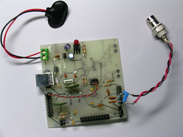
Parts side

  • The red and black braided wire connects FX2 CLKOUT pin to FX2 IFCLK and ADC ENCODE pins
  • The two jumpers in the top left corner are "SELF POWER" (to use USB power, this one is closest to the USB connector) and "CURRENT" - to make current consumption measurements
  • The absent 8-pin IC is the I2C flash chip - I just program FX2 as it comes up with default Cypress USB ids.
  • The BNC connector you see on the right is connected to simple 50-ohm "analog frontend" that configures ADC chip for single-ended operation (it is described in the ADC datasheet). This is convenient for connecting to test equipment like signal generators.
  • This layers is marked as "SOLDER SIDE" in PCB layout. This is because I was concentrated on getting connections to surface mount chips that are on the other side.

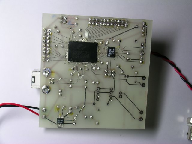
Surface mount side

  • You can clearly see CY7C68013 "FX2" chip, AD9283 ADC chip and the 3.3V voltage regulator LTC1763 made by Linear Technology
  • The toughest part of making this board was soldering the FX2 chip. I wish they came out with a package with larger pin spacing !
  • Earlier board revisions used MAXIM ADC's - these have even tighter pin spacing than FX2 and, as you can imagine, this did not work out that well.
  • When I first assembled the board it did not work - which was in stark contrast to the SR-1 project I assembled earlier. After much tinkering it turned out that if I press on FX2 chip hard enough it would show itself to USB bus. Presumably poor connections were to blame. I redesigned the board to allow for longer pads so it is easier to solder, but it is still tricky.
  • The little "1" markings show where the first pin of the IC is, so it is easier to place them correctly.
  • Note that the USB connector is on the other side.

Screenshot

  • This screenshot shows fx2_viewer (part of fx2_programmer) displaying waveform and Fourier transform in real time.
  • Since, like fx2_programmer, fx2_viewer uses libusb for input/output I have not been able to get more than 9 MB/sec - this is less than my best number benchmarked before. Probably something inside Linux kernel or libusb has changed since.
  • The firmware running inside FX2 is available from CVS, module 8051, subdirectory SR-7.

Making your own

I have not bothered to make a schematic as the design is a straighforward combination of FX2 ATA evaluation board (chop off ATA connector) and AD9283 evaluation board (chop off all ICs except AD9283).

I did, however, write a bunch of Tcl/Tk scripts that serve a similar function (have a description of all connections) and produce a preliminary layout for PCB. You can think of them as a "TeX for boards" (note: it is *not* as easy as LaTeX so some tweaking is required to position parts and make traces).

The SR-7.0j PCB layout was created with the wonderful PCB program. Futurlec had no problem producing it from Gerber files generated by PCB. Note: I did not order silk screening, so it is somewhat screwed up on the board layout - overlaps parts, etc.

Here are some notes on board assembly in case anyone wants to tinker with their own board:
  • First, take a bare USB connector, hook it up to the cable and find the power supply pins. Your multimeter should show 5 V
  • Insert the connector into the board and check that you can see the voltage where they are supposed to be (i.e. that ground is ground). If all is ok solder the connector into place and check that it is correct and the computer does not complain about over-current conditions on USB ports (which would indicate a short).
  • Solder the parts for voltage regulator LTC1763. These are
    • REG_SWITCH jumper (short it to use USB power)
    • Voltage regulator REG (watch for pin 1)
    • Capacitors C17 (0.01 microFarad - exactly), C18 (about 4.7 microFarad), C16 (about 6.3 microFarad)
    • LED network: POWER_LED (use a small current LED) and R6 (1K) (you might want just to insert LED first to make sure the polarity is right)
    Install a jumper on SELF_PWR connector. Check that the LED lights up and you see 3.3 V - exactly !
  • Time for bravery ! We are going to solder FX2 chip parts:
    • Crystal oscillator: XTAL, capacitors C8 and C9 (22pF each)
    • I2C network resistors R10 (1K) and R12 (10K) - without these FX2 will not enumerate properly
    • Reset and wakeup networks: R2 (100K) , R5 (10K), C12 (0.1 microFarad)
    • Bypass capacitors C3, C20, C1, C19, C2 - use ceramic ones about 0.1 microFarad each. I suggest not soldering all of them at once to leave space for higher (or lower) value ones in case they are needed.
      However, solder at least C3, C20 and C19.
    • Position FX2 chip - make sure first pin is correct. Solder pins on oppossing ends and then do the rest.
    • I found convenient to use a very fine-tip soldering iron at around 275 Celcius. Just tin it and touch at the butt end of the pin until the solder melts underneath. It would help if there is a tiny bit of solder on the iron tip itself.
    • If you get solder stuck between FX2 pins just bruch with the iron tip away from the chip making sure to melt the stuck bit and clean iron tip from solder between tries.
    • When all done connect the device to USB port and check that it enumerates correctly. You can also play with FX2 chip using some of the 8051 scripts in CVS.
  • Once you know that FX2 chip is working right, solder on the rest.
    • solder the connectors for ADC, FX2 D and C ports, CLKSWITCH
    • Solder R3 (10K) and R4 (100K) resistors - they make sure ADC is powered down when the board is first plugged in
    • Solder capacitor C8 (0.1 microFarad)
    • Solder the rest of bypass capacitors - this does not hurt.
    • You can omit the drossel L1 - it is there to provide additional isolation for ADC analog supply. I found out it is not necessary.
    • Position AD9283 chip, check that pin 1 is where it is supposed to be. Solder opposing pins first. You will find this much easier than soldering FX2 chip.
    • There is a place solder EEPROM (or better yet - an IC socket for EEPROM), I did not bother with this.
    I also suggest you assemble a simple 50 Ohm frontend to connect to "ADC testpoint block". At the very least place a jumper shorting REFIN and REFOUT pins.
  • To test ADC operation you would need to program FX2 with appropriate firmware. You can find the one I used in CVS, module 8051, subdirectory SR-7. Make sure to place a jumper connecting IFCLK FX2 pin to ENCODE input of ADC. (use CLKSWITCH block). You might also want to connect CLKOUT FX2 pin to IFCLK and ENCODE (see pictures).

Parts list

  • CY7C68013 "FX2" chip - probably the most expensive part in the design. You might want to replace it with pin-compatible lower-power version (see Cypress website).
  • AD9283 ADC chip
  • LTC1763 3.3V voltage regulator
  • Connectors: USB B connector, single and double row headers. I suggest you also get some BNC socket connector (you might want to get several). Get also some RG58 BNC plugs and RG58 cable to match them. Of course, the choice of RF connector is somewhat arbitrary :)
  • 24 Mhz crystal as described in FX2 datasheet
  • Several resistors: 1K, 10K, 100K. You would want 50 ohm and 25 ohm resistors for the simple ADC frontend.
  • Several ceramic capacitors: 22pF, 0.1microFarad, 0.01 microFarad.
  • A couple of electrolytic capacitors: 4.7microFarad, 6.3microFarad. You can use tantalum if you like.
  • A small current LED - use one that lights up at 3mA.
  • A stock USB 2.0 cable (plain USB 1.1 might not work right).

Frontends

So far I only have a hastily sketched schematic of 50 ohm BNC frontend and photodiode one. Hopefully this gives some idea of how to use the board. I'll post more as they become available (perhaps learn to use gschem along the way).

Links and References

IC manufacturers

Open Source Tools

Miscellaneous

SR-1/Software Radio

http://volodya-project.sourceforge.net/SR/SR-1/sr1.php


Overview

Before implementing full blown software radio I needed to become familiar with CY7C68013 and to answer a few questions:

  • How much data can it pump thorough ?
  • How much data can linux USB driver handle without overburdening cpu too much ?

Also it would be a good idea to develop a few tools that would become useful later.

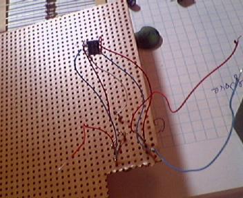
Hence, SR-1: a usb device that is just CY7C68013 without anything to pass data from.

Components

I ordered my parts from Arrow electronics website. This went ok, except that the shipping was too much. I understood why after I got three packages: a large envelope, a carton triangular box (the one to ship posters in) and a long carton box. Turns out that they shipped the parts in standard packaging, even though I ordered only few chips each. Here is a photo of the long tray CY7C68013 came in:

Image of the tray with CY7C68013 chips

Not only that, but they also shipped the parts from three different locations.

Note to self: if ordering low quantity parts from Arrow Electronics again order as few different kinds as one can and get others from someplace else that ships from a single address.

The ICs I am going to use in SR-1 are voltage regulator Linear Technology LTC1763-3.3V

Image of LTC1763 chip

and EZ-USB FX2 chip from Cypress CY7C68013

Image of CY7C68013 chip

Both are surface mount components, here is a photo of them side-by-side:

Image of all ICs used side by side

Design

Ok, this should have really preceded the component part, but I thought it would be more fun to take a look at the pictures first.

Since this would be the first time I am using these ICs and there will be plenty of corners to cut later I decided to replicate most of the Cypress ATA reference design CY4611 design, but without the EEPROM and the ATA connector.

On to soldering !

The first task was to wire up the voltage regulator LTC1763 and check that it produces the correct voltage (3.3V).

Connected voltage controller chip

one more shot of image controller

This proved easier than I thought as there was plenty of clearance between the legs of the chip. A quick test proved it functions correctly.

The hard part

Looking at the dense spacing of CY7C68013 pins prompted (yet another) trip to Radio Shack, and I purchased a "helping hands" - a kind of static holder with a magnifier glass.

Image of static holder with a magnifier lens

The grippers turned out to be really handy, but the magnifier glass needed to be too close to work to solder comfortably. It did find its use later, though.

I decided to attach wires to each pin that I am going to use first, and then attach the wires themselves to the other parts.

The first two were easy:

Image of CY7C68013 chip with two wires attached

The third was harder, and after trying to attach the fourth it came off:

Image of CY7C68013 chip with three wires attached

Time to do some thinking !

Image of me thinking

After much experimentation I decided to bend every other pin up. This increased the amount of space between pins threefold. Bending is much easier with the magnifier glass.

Image of CY7C68013 with every other pin bent up

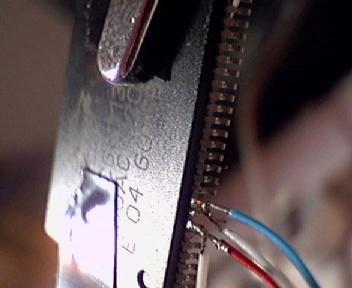
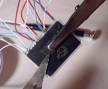
First side had the most wires. The blue ones are for ground, red ones for power and whites ones for everything else. Since both USB and I2C are serial buses there are few white wires.

Image of CY7C68013 with one side wired up

Feeling somewhat exhausted I decided to continue with this project after a good nights sleep.

Fortunately attaching the rest of the wires did not prove more challenging

Image of CY7C68013 chip completely wired up

Assembly

Now is the time to connect everything together. This involved more soldering, during which some of the wires I so carefully attached to CY7C68013 came loose. No matter, now that I knew how to do this reattaching was trivial.

Image of SR-1 device complete

Testing

Now that SR-1 is complete it is time to plug it in.

For the first test I decided to restrict myself to USB-1.1 even though the part supports 2.0. This way I can plug it in into a USB hub which would be cheaper to replace if anything went awry. Granted, USB standard includes overcurrent and ESD protection, but some caution would not hurt. Besides, this allows me to be closer to my monitor and keyboard.

After plugging it in, Linux (2.4.16) bitterly complained about a new device that just does not want to enumerate.

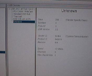
After spending lots of time browsing and searching for relevant links I decided to enable debugging in USB module. Voila ! It works :))

Image of KDE USB info panel showing device connected and enumerated

Here is a shot of dmesg output:

Image of dmesg output showing the device descriptors

Apparently the debugging introduced some delays that allowed it to enumerate properly. This does not seem to be needed when connecting to USB 2.0 adaptor card so it might not be a hardware fault after all

Now that the device enumerated it was time to access its internal memory. After some quick programming I had created an fx2_programmer utility that used libusb to talk to CY7C68013.

Programming 8051

CY7C68013 contains an internal microprocessor that is opcode and register compatible with Intel 8051. Thus one can use the excellent SDCC compiler to write programs for it, instead of doing everything in machine code.

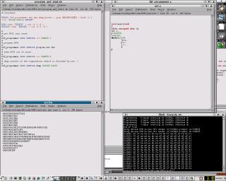
A quick update to fx2_programmer allowed me to upload Intel hex format files and test my first program that fills a predefined area with cycling integer numbers.

ex3 output screenshot

The above image is only a thumbnail, if you click on it you get the whole screenshot showing program code, compiled Intel hex format file and the dump of 8051 memory space after the program has run.

The strange xdata qualifier for the pointer p indicates that it points to the "external" memory. The reason is that 8051 is an 8 bit microprocessor and the most you can address with 8 bits is 256 bytes.. But read the manual to get the details - they are fun :)

Benchmarks

Now that everything works it is time to do some benchmarking. I connected SR-1 to ehci adaptor (no need to turn on debugging here) and wrote a small C program instructing 8051 to fire up bulk out buffers as soon as it can (ex3 in the 8051 code tarball). The best result I got was around 4 MB/sec - achieved but eliminating all 8051 code, including the NOPs recommended by the datasheet.

It turns out that changing packet size from 512 to 64 in ex3.c has little effect on the throughput. However, when I instruct fx2_programmer to read in 64 byte chunks instead of 512 the rate slows down to around 512 KB/sec.

Increasing chunk size beyound packet size yielded rediculous results - rate in excess of 50 Mb/sec for chunk size 65536.

After some digging it looks like something among usb driver and libusb screws up when user application requests to receive more than 64 byte packets, but the USB device only wants to send data in 64 byte chunks.

When I changed ex3.c to send data in 512 byte packets again things became more sensible and the rate peaked at 16 MB/sec with chunk size 2048 bytes.

The cpu utilization was quite small - less than 5%

Conclusion

The device functioned correctly. The achieved throughput rate was quite respectable and sufficient for real time data capture. The system remained almost idle during transfers.

Links and references


Linux and USB 2.0

Linux and USB 2.0

Last Update: 29 November 2004

This is a short writeup explaining what USB 2.0 changed and what's going on with it in Linux. It starts by talking about user visible changes (including usbfs information) followed by driver-visible ones. Finally it summarizes the current state of Linux USB 2.0 driver support in recent 2.4 and 2.6 kernels. If you want assistance getting this working on your hardware, try the linux-usb-users (or linux-usb-devel) mailing lists at http://www.linux-usb.org.

If you're a 2.4 user, use 2.4.22 or newer kernels. Newer kernels (including 2.6.x ones) have updates which seem to resolve the worst problems reported. The driver version string should be no older than June 2003. (VT6202 problems may still remain, especially on 2.4 kernels.)

Some older Linux distributions ship 2.4.18 kernels with EHCI code based on much older code, similar to what was in 2.5.2; the newer code supports more hardware, fixes bugs, is smaller, and has other goodness. If you're building a distribution, avoid using such old code; in particular, 2.4 versions of the EHCI driver are no longer being kept current.

You should probably know that "USB" is an abbreviation of the Universal Serial Bus, which is widely used for peripherals in modern desktop systems. (It's not "universal" in the sense that you'd want it instead of HyperTransport!) PCs typically support one or more USB controllers (one per "USB bus") each of which can support up to 127 different USB peripherals. "Legacy free" PCs omit non-USB peripheral support (like RS-232 serial lines, and PS/2 ports). Partially excepting the new USB 2.0 "OTG" support, USB is asymmetric. For example, its cabling is always asymmetric (even with OTG), so you can't hook things up incorrectly. USB supports "hotplugging" for all its peripherals, which means that you don't have to configure them by hand and that peripherals may rely on power delivered through USB. Both those features help reduce end-user setup and configuration problems, which was a major goal for USB technology.


OS-Neutral Changes in USB 2.0

Today, most USB peripherals and hosts support USB version 1.1, which supported two device speeds: low speed at 1.5 Mbit/sec, and full speed at 12 Mbit/sec. USB 2.0 is appearing in current product designs, and one of its main features is adding a new speed: high speed, at 480 Mbit/sec.

To put it another way: USB 1.1 was OK for low speed devices like mice and keyboards, and even for medium speed ones like Ethernet (10 Mbit/sec) adapters, or consumer electronics gadgets that only exchange a few megabytes of data (like many digital still cameras and MP3 players). USB 2.0 "full speed" or "low speed" is effectively just the familiar old "USB 1.1". You need USB 2.0 high speed to get reasonable speed for multiple large transfers as with some PC peripherals like disk drives (including MP3 jukeboxes :) or high resolution webcams (USB video), or get concurrent use from a bunch of 100BaseT networking adapters.

OK, it's faster! ... but what else will a Linux user notice about USB 2.0? We'll go from the outside in: starting from what you'll see with product boxes, and then working toward what you'll see with normal Linux user mode tools. (More technical details are in later sections.) One thing you won't notice is designed-in compatibility problems. Apart from some constraints on how you set up high speed devices, all your USB 1.1 hardware works just fine with USB 2.0 systems.

Updated USB Logos

One thing that you should watch for, and use to your advantage, is a new testing and branding program. Earlier USB peripherals sometimes had compatibility problems, and the tighter electrical requirements of USB 2.0 could have aggravated that issue. Instead, there are new USB 2.0 logos and a testing program that must be passed before peripherals are allowed to use them. That is, this isn't purely a marketing gimmick, there's actually some value wrapped up in this logo. Here are the new and old USB logos:

New USB 2.0 Logo
high speed labeled by the top stripe ... the two-color version highlights that in red, sometimes it's one-color.
Old USB 1.1 Logo (no compatibility testing done)

Be cautious about "high speed" peripherals that for any reason don't display that new logo. Those devices may not work very well, and it'll be your fault for encouraging vendors that sell nonconformant devices.

Hubs and Cabling

One big win for the USB 2.0 upgrade is that cables don't need to change. With the possible exception of some low quality cables that may not even handle USB 1.1 very well, you can keep using your existing USB cables. There was no need to switch to optical signal transmission, or anything similarly incompatible. There are new "Mini-B" cables, that can help eliminate the need for proprietary connectors on many small USB peripherals. (Think of a camera, cell phone, or PDA; classic B sockets take up way too much space.) However, some people report they need to avoid using long USB cables. If you're using long cables and having problems enumerating, try using shorter cables.

USB 2.0 hubs are special. Not only do they support high speed devices (older USB 1.1 hubs can't), but also because they all include "transaction translator" support that helps prevent full and low speed devices from wasting most of the USB bandwidth. See the later section on backwards compatibility for information about how this impacts end users with high speed buses whose devices may not all operate at high speed.

USB "On-The-Go" (OTG)

There is also a supplement to USB 2.0 called USB "On-The-Go" (OTG) which supports point-to-point peer style hookups for USB devices that are often used without a PC host. Few end-user OTG products exist yet; newer embedded Linux systems can be used to implement them. OTG relies heavily on those new USB "Mini" connectors, and supports low power operation (battery friendly). It also defines a modified USB 2.0 logo:

USB OTG Logo
full-speed version
(without high speed top stripe)

The key change in OTG is defining a new "Dual-Role" type of peripheral, which can become a low-power USB host when you connect it to another peripheral. Most OTG-capable peripherals will have special Mini-AB sockets (new in OTG). Because of how the USB "mini" plugs and jacks work, Mini-AB sockets accept either the Mini-B peripheral jack at one end of a USB cable or the (new in OTG) Mini-A host jack at its other end. Use the peripheral end, and they start out as a peripheral. Use the host end, and they start out like a USB host ... so that you could print directly from your camera or phone, hook a keyboard up to your PDA, or swap songs with your friend's MP3 player. If you connect two different dual-role devices, the "wrong" one may be initialized as the host. In that case, the optional OTG Host Negotiation Protocol (HNP) lets devices switch roles between "host" and "device" instead of forcing users to switch the cable around.

Host Controllers and Backwards Compatibility

You can connect USB 2.0 peripherals to USB 1.1 hosts and hubs, and they should work just fine ... but at 12 Mbit/sec, not at 480 Mbit/sec.

To get "high speed" behavior you'll need an updated host controller. It must support "USB 2.0 high speed", through the "EHCI" standard. Today you can get those as PCI cards, usually with a three or five port controller from NEC, or sometimes a four port one from Philips or VIA. More importantly, essentially all current generation PC motherboard silicon includes an EHCI controller built in. Linux users have reported success on most of these, with chips from ALI, Intel, NVidia, SiS, VIA, and others. (That's in alphabetical order; I'm not intending to slight any vendors.) See the section on Linux support (later) for more specific information.

You may also need newer hubs with USB 2.0 support. Probably the most important aspect of such hubs is how they support trees of devices that mix both high speed and full (or low) speed devices. The short version of the story is that to get high speed transfers out of a high-speed capable device, you must hook it up through an EHCI controller (that's using an EHCI driver!), and any hubs between the host and the device must only be USB 2.0 hubs.

That is, a tree of USB devices can start out with a high speed root hub, but if you plug in any USB 1.1 hubs to that tree, USB devices on branches below that hub will only operate at slower full/low (USB 1.1) speeds ... even if it's a USB 2.0 device. For now the lesson is that if you want to use a device at high speed, double check it after cabling things up. You can do this with "usbfs".


Changes Visible to Linux Users

Beyond those general issues, Linux users will notice a few changes if they poke around through what the kernel tells them about their hardware.

"usbfs" and /proc/bus/usb/devices

You may know "usbfs" through its original, and somewhat confusing name, of "usbdevfs". The name changed because it was completely unrelated to "devfs".

If you use "usbfs" (perhaps through scripts like usbtree or tools like usbview) you will notice a few minor changes. Most notably, the USB version for some devices will be "2.0", and those devices will report their speed as "480Mb/s" when they're running at high speed. (In compatibility mode, at full speed, they'll say "12Mb/s".) Here's what usbtree shows for some full speed devices hooked up to an USB 2.0 controller. Several are connected through a USB 2.0 hub, and there's a USB 1.1 hub (with no devices) hooked up to another root hub port.

/:  Bus 03.Port 1: Dev 1, Class=root_hub, Driver=ohci-hcd/2p, 12M
/: Bus 02.Port 1: Dev 1, Class=root_hub, Driver=ohci-hcd/3p, 12M
|__ Port 1: Dev 2, If 0, Class=hub, Driver=hub/4p, 12M
/: Bus 01.Port 1: Dev 1, Class=root_hub, Driver=ehci-hcd/5p, 480M
|__ Port 2: Dev 2, If 0, Class=hub, Driver=hub/4p, 480M
|__ Port 1: Dev 3, If 0, Class=>ifc, Driver=pegasus, 12M
|__ Port 4: Dev 8, If 0, Class=hub, Driver=hub/3p, 12M
|__ Port 1: Dev 9, If 0, Class=HID, Driver=hid, 12M

Some of the endpoint descriptors may change. Maximum packet sizes can be bigger, and polling intervals for periodic transfers will sometimes be measured in microseconds (like 250us), not milliseconds (like 2ms), and you may even see NAK rates for bulk endpoints. For example, this descriptor is for one USB 2.0 CD-RW when it's running at high speed:

T:  Bus=01 Lev=01 Prnt=01 Port=01 Cnt=01 Dev#=  2 Spd=480 MxCh= 0
D: Ver= 2.00 Cls=00(>ifc ) Sub=00 Prot=00 MxPS=64 #Cfgs= 1
P: Vendor=05ab ProdID=0060 Rev= 2.10
S: Manufacturer=In-System Design
S: Product=USB Storage Adapter
S: SerialNumber=2201010A0247C8AB
C:* #Ifs= 1 Cfg#= 2 Atr=c0 MxPwr= 98mA
I: If#= 0 Alt= 0 #EPs= 3 Cls=08(stor.) Sub=06 Prot=50 Driver=usb-storage
E: Ad=01(O) Atr=02(Bulk) MxPS= 512 Ivl=125us
E: Ad=82(I) Atr=02(Bulk) MxPS= 512 Ivl=0ms
E: Ad=83(I) Atr=03(Int.) MxPS= 2 Ivl=32ms

Here's the descriptor for the same CD-RW when there's no EHCI driver, so it's running at full speed (may not be a good idea to burn CDs at this speed though):

T:  Bus=02 Lev=01 Prnt=01 Port=00 Cnt=01 Dev#=  2 Spd=12  MxCh= 0
D: Ver= 2.00 Cls=00(>ifc ) Sub=00 Prot=00 MxPS=64 #Cfgs= 1
P: Vendor=05ab ProdID=0060 Rev= 2.10
S: Manufacturer=In-System Design
S: Product=USB Storage Adapter
S: SerialNumber=2201010A0247C8AB
C:* #Ifs= 1 Cfg#= 2 Atr=c0 MxPwr= 98mA
I: If#= 0 Alt= 0 #EPs= 3 Cls=08(stor.) Sub=06 Prot=50 Driver=usb-storage
E: Ad=01(O) Atr=02(Bulk) MxPS= 64 Ivl=0ms
E: Ad=82(I) Atr=02(Bulk) MxPS= 64 Ivl=0ms
E: Ad=83(I) Atr=03(Int.) MxPS= 2 Ivl=32ms

Other than that "480Mb/s" speed rating, most of that per-device usbfs information will only be interesting to folk working with device drivers. That "480Mb/s" in the descriptor for your device will be a sign that you've cabled it up correctly (so it runs at high speed). But there are also differences you may notice if you look at the root hub support for each of your systems USB busses.

USB 1.1 "Companion Controllers"

Perhaps the most curious thing is that when you plug in a full (or low) speed device to a connector on your high speed USB controller, it will be connecting to a different bus than when you plug in a high speed device to that same USB "A" socket on your PC! In the CD-RW example above, the bus number changed. Sometimes the port number will also change. (OK, so maybe you wouldn't have noticed.)

That's because of how the controllers work. Here's how /proc/bus/usb/devices looks on one system with a five port NEC EHCI based controller, and nothing hooked up to it. I added some whitespace and highlighting so you can see what's going on a bit better:

T:  Bus=03 Lev=00 Prnt=00 Port=00 Cnt=00 Dev#=  1 Spd=12  MxCh= 3
B: Alloc= 0/900 us ( 0%), #Int= 0, #Iso= 0
D: Ver= 1.10 Cls=09(hub ) Sub=00 Prot=00 MxPS= 8 #Cfgs= 1
P: Vendor=0000 ProdID=0000 Rev= 2.05
S: Manufacturer=Linux 2.5.8 ohci-hcd
S: Product=NEC Corporation USB
S: SerialNumber=00:0b.0
C:* #Ifs= 1 Cfg#= 1 Atr=40 MxPwr= 0mA
I: If#= 0 Alt= 0 #EPs= 1 Cls=09(hub ) Sub=00 Prot=00 Driver=hub
E: Ad=81(I) Atr=03(Int.) MxPS= 2 Ivl=255ms

T: Bus=02 Lev=00 Prnt=00 Port=00 Cnt=00 Dev#= 1 Spd=12 MxCh= 2
B: Alloc= 0/900 us ( 0%), #Int= 0, #Iso= 0
D: Ver= 1.10 Cls=09(hub ) Sub=00 Prot=00 MxPS= 8 #Cfgs= 1
P: Vendor=0000 ProdID=0000 Rev= 2.05
S: Manufacturer=Linux 2.5.8 ohci-hcd
S: Product=NEC Corporation USB (#2)
S: SerialNumber=00:0b.1
C:* #Ifs= 1 Cfg#= 1 Atr=40 MxPwr= 0mA
I: If#= 0 Alt= 0 #EPs= 1 Cls=09(hub ) Sub=00 Prot=00 Driver=hub
E: Ad=81(I) Atr=03(Int.) MxPS= 2 Ivl=255ms

T: Bus=01 Lev=00 Prnt=00 Port=00 Cnt=00 Dev#= 1 Spd=480 MxCh= 5
B: Alloc= 0/800 us ( 0%), #Int= 0, #Iso= 0
D: Ver= 2.00 Cls=09(hub ) Sub=00 Prot=01 MxPS= 8 #Cfgs= 1
P: Vendor=0000 ProdID=0000 Rev= 2.05
S: Manufacturer=Linux 2.5.8 ehci-hcd
S: Product=NEC Corporation USB 2.0
S: SerialNumber=00:0b.2
C:* #Ifs= 1 Cfg#= 1 Atr=40 MxPwr= 0mA
I: If#= 0 Alt= 0 #EPs= 1 Cls=09(hub ) Sub=00 Prot=00 Driver=hub
E: Ad=81(I) Atr=03(Int.) MxPS= 2 Ivl=256ms

Yes, three USB buses on one controller card! (The PCI card is 00:0b but each bus has a different PCI function number.) And it looks like there's a total of ten ports (sum the "MxCh" entries saying how many children the root hubs have), not five ... how can that be?

The answer is that the two OHCI "companion controllers" are used along with the EHCI controller, and a silicon switch connects each port to only one controller at a time. When an EHCI driver runs, all ports start out connected to EHCI. When EHCI detects a full or low speed device on a port, that port is switched over to one of the companion controllers. High speed devices it keeps for itself ... so each port seems to connect to either EHCI or its companion controller (never both!) based on whether it runs at high speed or not. If there's no EHCI driver there to handle high speed devices, then everything gets treated as full or low speed since the switch won't connect things to the EHCI controller. (Companion controllers won't necessarily be OHCI; some are UHCI.)

So to fully use a USB 2.0 host controller you must still use an OHCI or UHCI host controller driver, as you've likely been doing already. And if that's the only driver you have, you can still use hardware that includes USB 2.0 support ... it just won't be as fast until you upgrade to an OS version with USB 2.0 support. In the big picture that's a great migration story for the core USB 2.0 technology: the hardware can upgrade, and the software follows later when it's convenient for end users. (Much like most vendors' stories for migrating from one generation of CPU, or instruction set, to the next one.)

The USB Host controllers in many embedded systems would rather not spend silicon for companion controllers, so some of them avoid this by embedding a transaction translator into the controller's root hub. That's not standardized, but Linux already supports one such product (from ARC).


USB 2.0 Hubs have "Transaction Translators" (TTs)

OK, this section talks about what makes USB 2.0 tricky. And it's not all that user visible, so you can safely skip reading it if you're one of the many Linux users who just wants a top quality OS (or a Free one) and aren't very concerned about all the underlying technology. If you want to skip this, remember just this one thing: hubs with more than one TT may support more active low and full speed devices, especially more webcams or audio devices.

If you're writing a device driver, you may want to know about this, since it can affect how you write your driver. At this writing, not all transaction translator features are used by Linux. Also, since those code paths aren't used much yet, a number of shortcuts have been taken, which limit throughput. (A mostly-functional patch is available for 2.6.10, removing those shortcuts.)

Split Transactions

USB 2.0 gets some of its backward compatibility through a technique called split transactions that's used in many other buses. Many disk interface technologies, for example, support concurrent requests to different devices (like USB does), and split their requests into a "start" phase, disconnecting, and reconnecting later for a "complete" phase. That lets the bus be used for other purposes while some slow I/O completes ... like a disk drive seeking and reading several sectors, or (in the USB case) like a 1.5 MBit/sec mouse delivering its motion event.

In the case of a USB 2.0 host talking to a USB 1.1 device, it does so either through a companion controller (so it's really acting as a USB 1.1 host), or through a transaction translator in a USB 2.0 hub. The host talks to the translator at high speed, and then the translator performs the full or low speed I/O to that USB 1.1 device. It buffers data in either direction as required, and later sends the results back to the host at high speed. A hub can have just one translator, or one per port. With just one translator, a hub can only use as much bandwidth as a USB 1.1 host can. With more translators, each port can use that much bandwidth.

So for example, each of the ports on the hub might have a full speed webcam, each of which is using ten megabits per second of I/O at the same time. With less capable hubs, only one port on that hub might be able to operate at that speed at a time, supporting only the bandwidth of a USB 1.1 bus.

Using Transaction Translators

From the perspective of a Linux USB 2.0 host, there are two ways it talks to USB 1.1 devices through transaction translators. Some requests do this almost transparently, like control requests and (full speed only) bulk data transfer. In those cases, the host must tell the EHCI controller that it's talking through a transaction translator, and maybe be ready to recover from some errors, but for most purposes there's control and bulk requests are completely "hands off". That means many USB 1.1 device drivers will continue to work just fine through a USB 2.0 hub ... many network adapters, modems, digital still cameras, MP3 players, disk drives, and similar devices won't need anything more.

Then there are the requests that need a lot of hands-on attention: periodic transfers like interrupt and (full speed only) isochronous ones. Because these are all reserved-bandwidth transacton types, they can't be automated as readily as control and bulk (which can opportunistically make progress whenever periodic transfers aren't active). The result is a lot of hub-related complexity in the EHCI driver, making sure that the periodic transfers are safely scheduled and that transaction translators don't get overcommited. Periodic transfers are already the most complex type in USB (though their API got simpler in the Linux kernel 2.6 series), so to some extent it's just one more consideration when scheduling,

For example, suppost a USB 1.1 periodic transfer is to be worked on every eight frames (milliseconds). That's going to go through a specific transaction translator; the transfer needs a time when that translator isn't in use, and when there's also bus bandwidth. The EHCI driver needs to schedule a "start split" (a bit in an 's-mask') sometime in one microframe, and a "complete split" (bits in a 'c-mask') in some later microframe, and ensure that between the start and completion no other request uses that translator. Isochronous transfers can be bigger, and are managed by EHCI using a different type of data structure, but in both cases you can see that there's a fair amount of housekeeping involved in tracking what requests are active.


Driver-Visible Changes in USB 2.0

The most visible change was the addition of "high speed" devices and transfers. In a Linux USB device driver, you can tell if the device is high speed (and thus whether its transfers will be at high speed!) by testing whether dev->speed == USB_SPEED_HIGH. You've been able to do that since about the 2.4.10 kernel, but you probably didn't have high speed devices to work with then.

The rules for full and low speed transfers have not changed, but some rules changed for high speed transfers. (You may have noticed some of those changes when comparing the high speed and full speed usbfs information shown above for the CD-RW.) In a few cases drivers need to have code that knows which rules apply, but mostly the changes will be transparent to correctly written drivers. Those changes include:

  • Maximum packet sizes for control transfers are fixed at 64 bytes, and for bulk transfers they are fixed at 512 bytes. For full and low speed, those limits are smaller and can also vary between devices. Don't hard-wire maxpacket sizes in drivers that will handle high speed devices (and their full-speed modes).
  • Maximum packet sizes for interrupt transfers can now be up to 1024 bytes. (For full and low speed, those limits are much smaller.) Likewise for ISO transfers (which previously had a curious 1023 byte limit).
  • There are now eight "microframes" per frame. A useful number to keep in mind is that thirteen bulk packets of 512 bytes each can be exchanged in one microframe. (At full speed, nineteen bulk packets of 64 packets could be exchanged in one frame. High speed transfers can be more than forty times faster than full speed ones!) For devices that can operate at high speed, drivers need to queue more data, both with bigger per-urb buffers and multiple urbs, to get the most benefit from that higher speed.
  • Periodic transfers can only reserve up to eighty percent of the USB bandwidth (per microframe). In USB 1.1, up to ninety percent was available.
  • Periodic transfer periods are measured in microframes, not frames. Both ISO and interrupt transfer intervals now use a log2 encoding, where previously only ISO transfers used that encoding. (Interrupt transfers can now have larger or smaller periods.) Drivers will need to interpret endpoint->bInterval differently for high speed devices, and also set urb->interval accordingly. Use usb_fill_int_urb() correctly, so this is done for you.
  • Periodic transfers can support a "high bandwidth" mode, where up to 3 packets (3KB at most) per microframe can be transferred. This shows up in a new field in endpoint descriptors. Drivers will need to interpret usb_maxpacket() differently for high speed, since that holds the new bit field as well as the original one. (With USB 1.1 devices, periodic transfers only involve one packet each period.)
  • EHCI provides less detailed error indicators than OHCI or UHCI. This means that drivers for USB 1.1 devices should retest for good behavior while connecting through a transaction translator in a USB 2.0 hub. Try things like unplugging devices while they're actively in use. It's likely they'll see EPIPE (endpoint stall) errors in some cases where previously they saw ETIMEDOUT (ohci) or EILSEQ (uhci). Unlike true endpoint stalls, usb_clear_halt() won't be able to talk to the device. (Your driver does have code to recover correctly from halted endpoints, doesn't it? It should!)

There are also protocol changes that should be invisible to most device drivers ... except in some cases for the host or device controller drivers, or the hub driver:

  • There's a new "other speed configuration" descriptor for devices that can work at both full and high speed. When a device is working at full speed, it would usually have different descriptors for high speed operation ... see the CD-RW example above. You don't need to re-enumerate at the other speed to see those descriptors.
  • "Split transactions" use a new feature of USB 2.0 hubs, the "transaction translator, which makes more efficient use of USB bandwidth. (All transactions run at high speed. Hubs build in buffering and logic for full or low speed speed operations.)
  • NYET transactions on the wire, used to detect that split transactions are not yet complete.
  • PING transactions on the wire help flow control to high speed bulk or control endpoints.
  • DATA2 and MDATA transactions on the wire are used with isochronous transfers.
  • The hub descriptor defines a few new fields, and uses the protocol number to say whether each port has its own transaction translator.

USB "Gadget" API; and OTG

As Linux gets embedded more widely inside USB peripherals (not just USB hosts), the USB "function" or "target" drivers have been getting more attention. The original Linux-USB programming interface had only a host side model: one master talking to many targets (like a web client talking to many servers). It didn't support the drivers running inside USB devices.

A peripheral side Linux-USB gadget API is now standard with 2.4 and 2.6 kernels. That framework currently supports at least a dozen different types of USB peripheral controller hardware under Linux. While it resembles the original host-side programming interfaces (at least in terms of submitting asynchronous requests, and in terms of shared core data structures), it must treat USB busses very differently from a host side API. That's because implementing the target function only involves responding to a single USB Host (like a web server only responding to one client at a time). Also, target side drivers can never initiate control requests, they can only respond to them.

Once Linux supported both "host" and "gadget" USB APIs (at all device speeds), it clearly had almost every programming interface needed to implement OTG compliant devices. Courtesy of Texas Instruments, Linux 2.6.9 kernels include an implementtion of OTG on Linux; that first implementation supports TI's OMAP processors, used in wireless devices.


Linux Status

People have been using USB 2.0 with usb-storage devices from Linux hosts since June 2001. But it was only towards the end of that year, a short while before Linus created the 2.5 development branch, that other USB 2.0 devices (notably, hubs) began to be available. So while some changes for USB 2.0 were rolling into 2.4 kernels through the year 2001, largely done by about 2.4.10, the most tricky stuff (the ehci-hcd driver) stayed separate until the 2.5 kernel branched. All current Linux distributions include EHCI support, and the end-user bug reports have been helping to stabilize that driver.

Host Controller Driver Support

At this writing the "ehci-hcd" driver is not as well proven as the OHCI or UHCI drivers, so parts of it (especially those parts interacting with USB 2.0 hubs and transaction translators) are still experimental, but it's just fine for many purposes, including espcially providing quick access to high speed disks. (Where "quick" often means up to 30 MByte/second, with off-the-shelf hardware.)

  • The Linux 2.6 kernel has the most up-to-date USB 2.0 support, as well as quite a number of other USB updates and cleanups.
  • The 2.4.19 kernel was the first to bundle a 2.4 based version of the ehci-hcd driver, but avoid using anything older than 2.4.22. Expect any 2.4 version to be less current than the 2.5 version; it's also not being updated to match 2.6 any more.
  • Older Linux distributions include a 2.4.18 based version that's much like the original 2.5 patch, though more recent distributions (including RedHat 9) match a good 2.4.21-pre level.

In terms of functionality, the latest driver:

  • Supports all four USB transfer types at high speed: control, bulk, interrupt, and isochronous. However, scheduling for interrupt transfers currently takes shortcuts which prevent them from using much bandwidth. (Or handling certain system configurations. However, a patch for 2.6.10 is being tested which removes those shortcuts.) And nobody's really done much yet with the isochronous code, although kernel 2.6.2 (or 2.4.25) and later has a rewritten version that handles high bandwidth, and is a lot more capable.
  • Has partial support for split transactions (full and low speed transfers) through USB 2.0 hubs:
    • Control and bulk transfers work, though older versions may not recover from some errors appropriately. That means: that while you should be able to use many USB 1.1 devices like disks and still cameras through such hubs, you might also run into some failure modes that can't yet be recovered. (And some device drivers might also need updates to handle new failure modes, as noted above.)
    • Full and low speed interrupt transactions work, taking the same scheduling shortcuts as high speed interrupt transfers take. So most keyboards and mice should work on USB 2.0 hubs, if you're using one of the more recent kernels. (Some serial port and Bluetooth adapters aren't compatible with those shortcuts though.)
    • Full speed isochronous transfers work somewhat through USB 2.0 hubs, in current 2.6 kernels. But they're not robust yet; for example, USB speakers will sometimes work, but there may also be an audible buzz in addition to (or instead of!) the desired sound. Eventually of course a dozen USB 1.1 webcams will easily coexist at full data rate on a single USB 2.0 bus, using USB 2.0 hubs.
  • The current kernels support BIOS handshaking (transferring "ownership" of EHCI from BIOS/SMM to Linux, as is done for OHCI or UHCI). That depends on EHCI hardware features that took time to become generally available with BIOS implementation support. Recently some BIOS versions have appeared which don't seeem to cooperate fully with Linux (mis-implementing that handshake).
  • Works with a variety of EHCI silicon implementations. NEC led the market by over a year, but now implementations from Intel, NVidia, Philips, VIA, SiS, ALI, Genesys, and others work with Linux.
  • Should tolerate more abuse on CardBus adapters. Before the 2.5.29 kernel, you needed to manually "rmmod" ehci-hcd (and often ohci-hcd) to cope with a sequencing bug in the CardBus shutdown.

You'll find that most PCI USB 2.0 add-in cards (and CardBus/PCMCIA ones) use the NEC silicon or the VT62x2, though there are other vendors. (Including ALI.) The cards that do both USB 2.0 and FireWire have for some reason been a problem for many people, even those without built-in PCI bridges. Avoid the VT6202 cards; but VT6212 should be OK.

Some folk have problems with the CardBus versions, because Linux hasn't always managed to get the IRQs assigned correctly on their particular laptop make/model. (IRQs are a general problem, BIOS and ACPI problems abound.) Once such BIOS/PCI level problems get resolved, the ehci-hcd driver works with those CardBus configurations too. It may be very important to use an external power supply for the CardBus adapter. (It seems like CardBus can't supply all of the power needed by bus-powered USB devices, without help: half an Ampere from each port. With longer USB cables, you may also need more power to drive the signals correctly.)

If you're using a CardBus adapter with an older driver version, you may need to manually remove the driver (with rmmod) before a CardBus eject (including cardctl eject) or system shutdown; the CardBus shutdown doesn't shut down drivers when it should, so that's the only "clean shutdown" solution..

See the linux/Documentation/usb/ehci.txt file in your Linux kernel source distribution for some more information. As always with drivers still in development, if you have any problems, try the latest code (preferably in the 2.5 kernel, otherwise in the latest 2.4 code) to see if the problem has been fixed yet. And if not, report problems to the linux-usb-devel mailing list.

Device Driver Support

High speed storage devices, and to some extent hubs, seem to be the most USB 2.0 devices so far. High speed scanners and printers are available, and there are early reports of success using them.

Most full and Low speed (USB 1.1) devices will work when connected to USB 2.0 root hubs, using their current drivers, since they'll be handled by the companion controllers. Many of them should also work when connected to USB 2.0 external hubs, subject to the restrictions desribed earlier. (Which, for the latest code, amounts to no webcam or audio support yet.)

Device Driver Comments
USB 2.0 hubs hub (usbcore) USB 2.0 hubs work, but haven't been widely stressed (especially in terms of faults happening during transaction translation). The hubs with Cypress hub chips have multiple transaction translators; get that kind if you're using many full speed audio or video devices.
Disks, CD-RW, USB-FLASH, etc usb-storage Linux USB 2.0 support seems to work pretty well for the usb-storage devices that now exist, though it's slower on 2.4 since the usb-storage driver does not queue its USB requests. (Where "slower" still tops 10 MByte/sec on most hardware.) Starting with about 2.5.45, storage uses the new usb_sg_submit() call to queue all I/Os in a scatterlist at once, so nothing should be in the way of letting your hardware achieve 20+ MByte/sec (except maybe bugs that aren't yet fixed, or slow disks).
BackPack USB Drives usb-storage Micro-Solutions has provided software to set up their devices with hotplugging, so that you can easily connect theeir drives to Linux. Available in several formats, including RPM.
Archos MP3 Jukebox usb-storage Older kernels may need a tweak to usb-storage error handling, or a workaround: start the Archos and let it boot up before you load or hotplug the usb-storage module..
ASIX AX88172 (10/100 Ethernet Adapter) usbnet A variety of products, including the D-Link DUB-E100, Hawking UF200, and Netgear FA120 all use this technology. Running at high speed, all of them should give much better throughput than similar full-speed products. This driver is merged into usbnet in 2.4 and 2.6 kernels.
ALI M5632 Host-to-Host Link usbnet Adapter cables based on this chip are available from several different vendors, and can provide good throughput to another Linux system.
IOGear Host-to-Host Link usbnet (patch needed) Press Release
Orange iBOT2 WebCam ovfx2, evolved from ov511 This is the first USB 2.0 webcam announced.
Cypress EZ-USB FX2 custom ... depends on what your firmware makes it do These are 8051 microcontrollers with support for high speed transfers, designed for use inside USB devices and with custom firmware. The fxload software lets you download that firmware. For the start of one interesting Linux-based example (hosted at sf.net), see the SR-1 software radio.
NetChip 2280 custom ... depends on what your firmware makes it do These are PCI based controllers with support for high speed transfers, designed for use inside USB devices and with custom firmware. Linux-USB gadget support is available, so you can implement that firmware under Linux. One such driver implemens a network interface, and others are under development.

Regardless of what type of high speed device you use, USB hotplugging works the same as it always has on Linux.

User mode device drivers should be able to use the usbfs APIs as usual. They may be able to tell that they're talking to USB 2.0 devices by details in the device descriptors (such as 512 byte bulk packets); the Java USB APIs expose such information more directly. The libusb APIs (in C) don't yet.


References